Method of driving 3-electrode plasma display apparatus to minimize addressing power

a technology of plasma display and addressing power, which is applied in the direction of instruments, static indicating devices, etc., can solve the problems of reducing the brightness of light emitted from the plasma display panel and generating unnecessary addressing power, and achieve the effect of preventing the generation of unnecessary addressing power

Inactive Publication Date: 2006-11-14
SAMSUNG SDI CO LTD
View PDF25 Cites 13 Cited by
  • Summary
  • Abstract
  • Description
  • Claims
  • Application Information

AI Technical Summary

Benefits of technology

[0009]The present invention provides a method of driving a 3-electrode plasma display apparatus, through which generation of unnecessary addressing power is prevented by adaptively reflecting the characteristics of video data.
[0011]According to the method of the present invention, the operation or non-operation of the power recovery circuit is controlled in accordance with the display data signals applied to the address electrode lines so that the characteristics of video data are adaptively reflected. Consequently, generation of unnecessary addressing power can be prevented.

Problems solved by technology

Unfortunately, as a result of using this driving method, in each subfield an address period increases and a display-sustaining period decreases, and, as a result, the problem is that the brightness of light emitted from the plasma display panel decreases.
In the above-described driving methods and others, unnecessary addressing power is generated because of the fact that the characteristics of video data are not taken into consideration.

Method used


Image

  • Method of driving 3-electrode plasma display apparatus to minimize addressing power
  • Method of driving 3-electrode plasma display apparatus to minimize addressing power
  • Method of driving 3-electrode plasma display apparatus to minimize addressing power

Examples


first embodiment

[0068]In the present invention, under the condition that the operation or non-operation of the power recovery circuit 63b is controlled for each subfield in accordance with display data signals of the subfield, an addressing power during the non-operation of the power recovery circuit 63b is predicted, and the power recovery circuit 63b is operated when the addressing power exceeds a predetermined reference value.

[0069]The following description concerns a method of predicting the addressing power. Through this method, the operation or non-operation of the power recovery circuit 63b can be controlled for each subfield in accordance with the display data signals of the subfield, and the operation or non-operation of the power recovery circuit 63b can also be controlled for each frame composed of the subfields in accordance with display data signals of the frame.

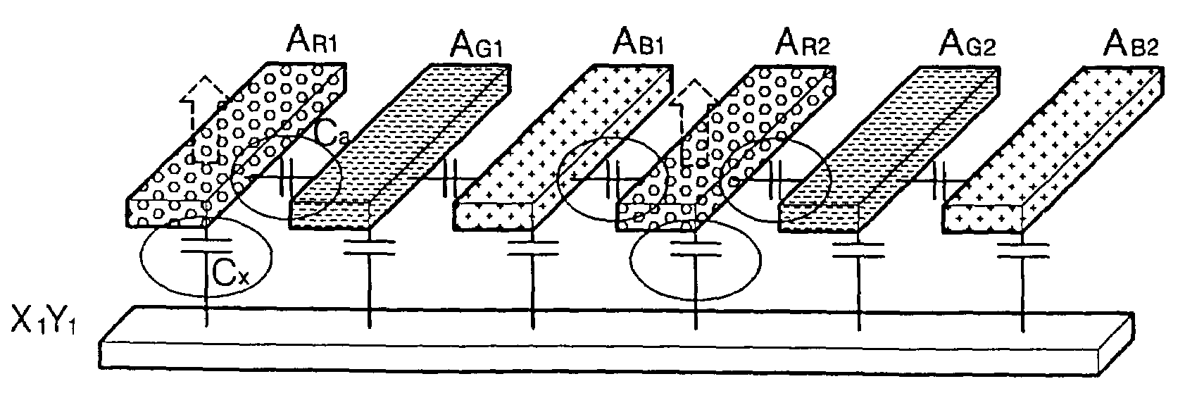
[0070]With respect to each of the XY-electrode line pairs X1Y1 through XnYn of a subfield to be displayed, a data variation b...

second embodiment

[0083]In the present invention, under the condition that the operation or non-operation of the power recovery circuit 63b is controlled for each subfield in accordance with display data signals of the subfield, an addressing power during the operation of the power recovery circuit 63b is predicted, and the power recovery circuit 63b is not operated when the addressing power exceeds a predetermined reference value.

[0084]The following description concerns a method of predicting the addressing power. Through this method, the operation or non-operation of the power recovery circuit 63b can be controlled for each subfield in accordance with the display data signals of the subfield, and the operation or non-operation of the power recovery circuit 63b can also be controlled for each frame composed of the subfields in accordance with display data signals of the frame.

[0085]With respect to each of the XY-electrode line pairs X1Y1 through XnYn of a subfield to be displayed, the number of disp...

third embodiment

[0093]In the present invention, under the condition that the operation or non-operation of the power recovery circuit 63b is controlled for each XY-electrode line pair in accordance with the display data of an XY-electrode line pair to be scanned first and the display data of an XY-electrode line pair to be scanned next, an addressing power during the non-operation of the power recovery circuit 63b is predicted, and the power recovery circuit 63b is operated when the addressing power exceeds a predetermined reference value.

[0094]A method of predicting the addressing power has been described above, and thus a description thereof will be omitted. Briefly, when it is assumed that a line data variation with respect to each XY-electrode line pair is n1·Cx, a coefficient of the line data variation n1·Cx is “a”, a cell data variation with respect to the XY-electrode line pair is n2·Ca, and a coefficient of the cell data variation n2·Ca of is “b”, an addressing power PALN between lines duri...


PUM


Abstract

A method of driving a 3-electrode plasma display apparatus including a 3-electrode plasma display panel, a video processor, a controller, an address driver, an X-driver, a Y-driver, and a power recovery circuit is provided. In the 3-electrode plasma display panel, X-electrode lines and Y-electrode lines are alternately arranged in parallel on the rear surface of a front transparent substrate so as to form XY-electrode line pairs, and address electrode lines are arranged on the front surface of a rear transparent substrate to cross the XY-electrode line pairs. The intersections between the XY-electrode line pairs and the address electrode lines define display cells. The power recovery circuit is included in the address driver. The power recovery circuit collects charges unnecessarily remaining in the display cells at the end of application of the display data signals and applies the collected charges to the display cells at the start of application of the display data signals. The operation or non-operation of the power recovery circuit is controlled in accordance with the display data signals applied to the address electrode lines.

Description

CLAIM OF PRIORITY[0001]This application makes reference to, incorporates the same herein, and claims all benefits accruing under 35 U.S.C. §119 from my application entitled METHOD OF DRIVING 3-ELECTRODE PLASMA DISPLAY APPARATUS TO MINIMIZE ADDRESSING POWER filed with the Korean Industrial Property Office on Jul. 12, 2002 and there duly assigned Serial No. 2002-40666.BACKGROUND OF THE INVENTION[0002]1. Technical Field[0003]The present invention relates to method of driving a flat display apparatus, and more particularly, to a method of driving a 3-electrode plasma display apparatus.[0004]2. Related Art[0005]Flat display panels have been becoming more and more popular as display devices. The combination of the thin depth and large display area has proven to be appealing to consumers. Efforts are being made to improve picture quality and reduce power demands associated with flat display panels.[0006]An exemplar of a recent effort in the art is disclosed, for example, in U.S. Pat. No. 5...

Claims


Application Information

Patent Timeline
Patent Type & Authority Patents(United States)
IPC IPC(8): G09G3/28G09G3/20G09G3/288G09G3/291G09G3/293G09G3/296G09G3/298
CPCG09G3/2022G09G3/2965G09G3/293G09G2330/021G09G3/296
Inventor KIM, JIN-SUNGEO, YOON-PHIL
Owner SAMSUNG SDI CO LTD
Why Eureka
Try Eureka