
Front teleconverter lens system

a technology of teleconverter lens and teleconverter, which is applied in the field of front teleconverter lens system, can solve the problems of insufficient optical performance, and achieve the effect of superb optical performance and sufficiently suppressing aberration production

Active Publication Date: 2006-11-14
NIKON CORP
View PDF6 Cites 4 Cited by
  • Summary
  • Abstract
  • Description
  • Claims
  • Application Information

AI Technical Summary

Problems solved by technology

Although the conventional front teleconverter lens system disclosed in the above-described document can be compact and lightweight with fewer lens and simple construction, aberration becomes slightly large, so that optical performance is not sufficient.

Method used


Image

  • Front teleconverter lens system
  • Front teleconverter lens system
  • Front teleconverter lens system

Examples


example 1

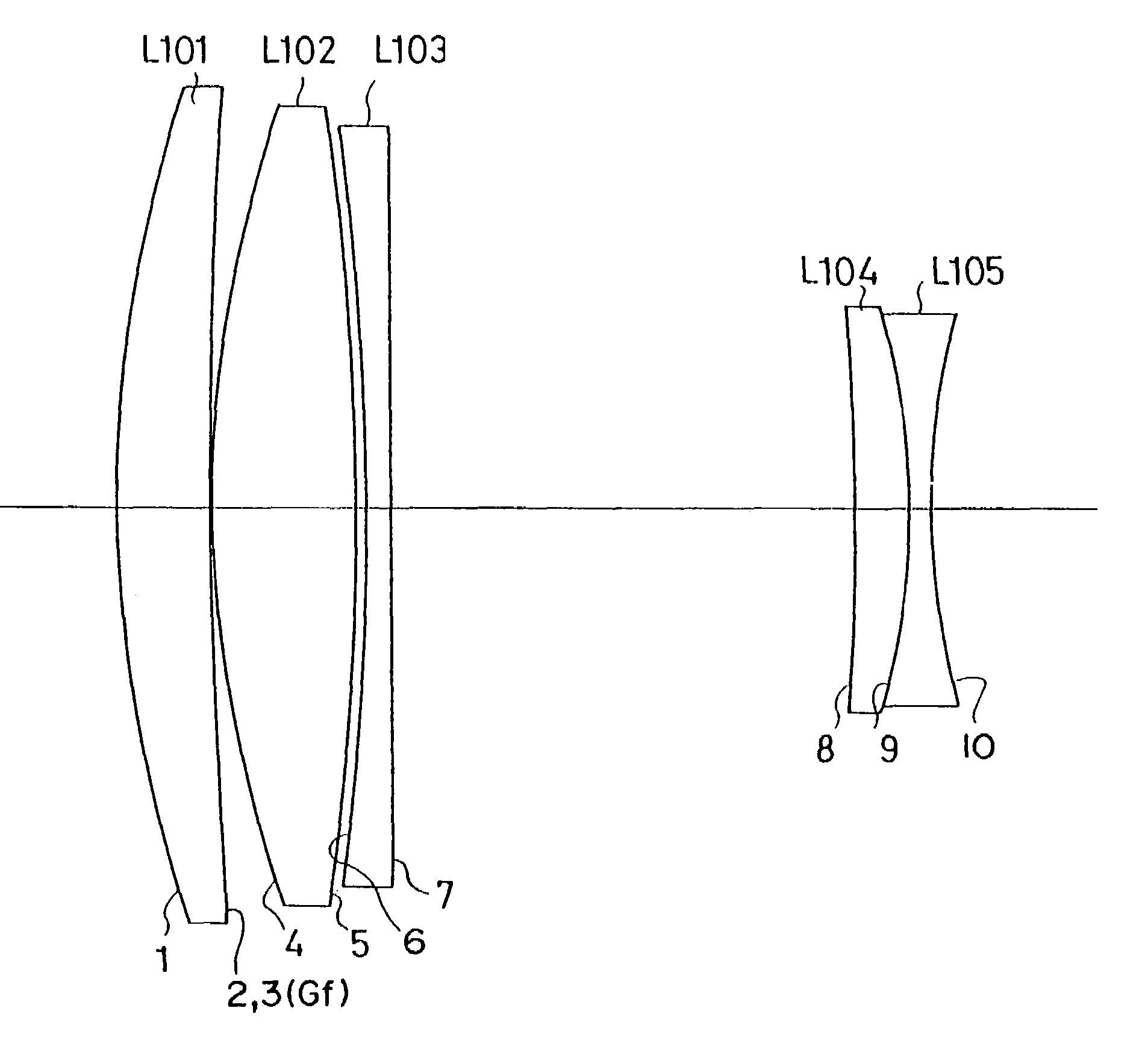
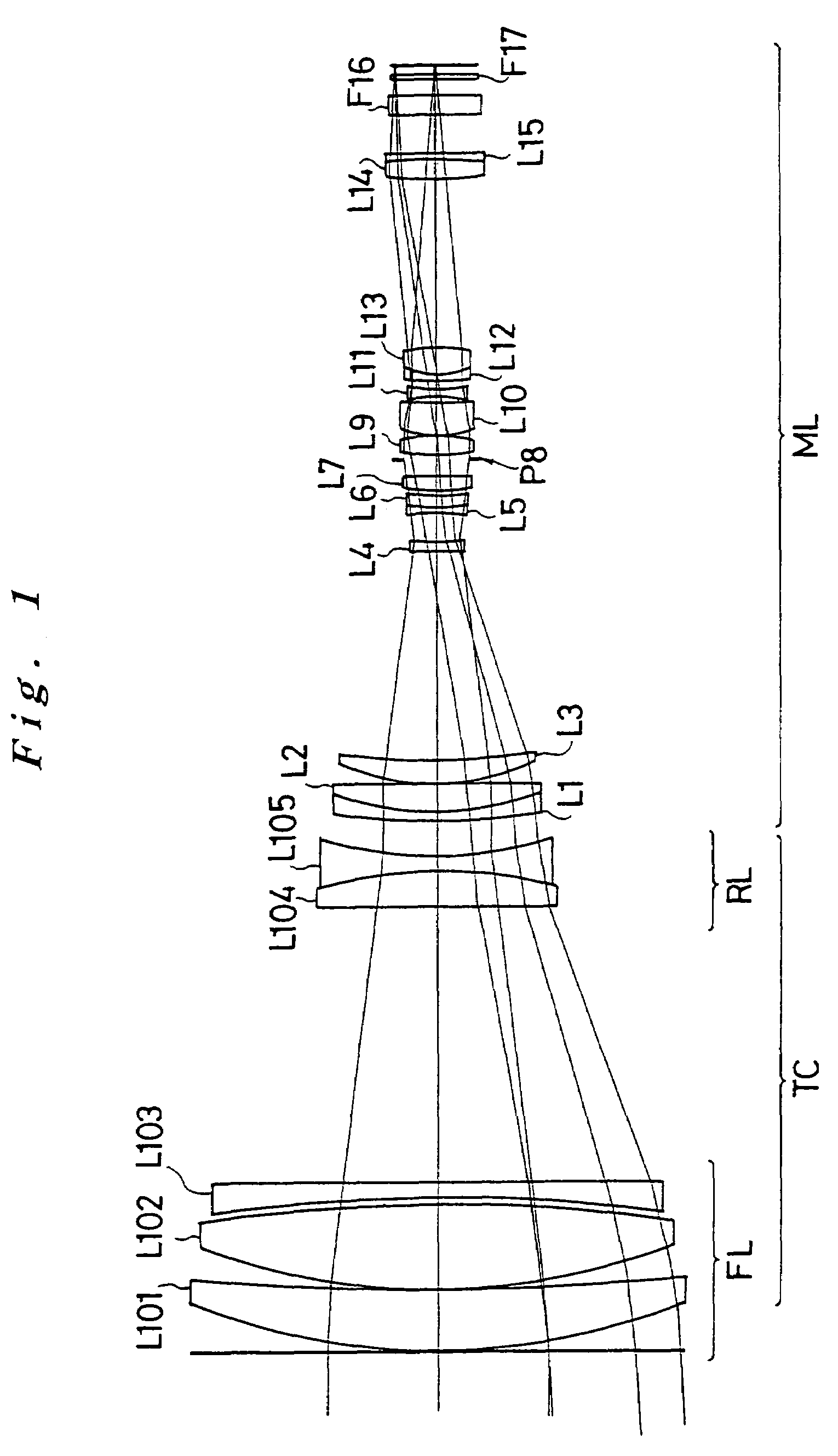
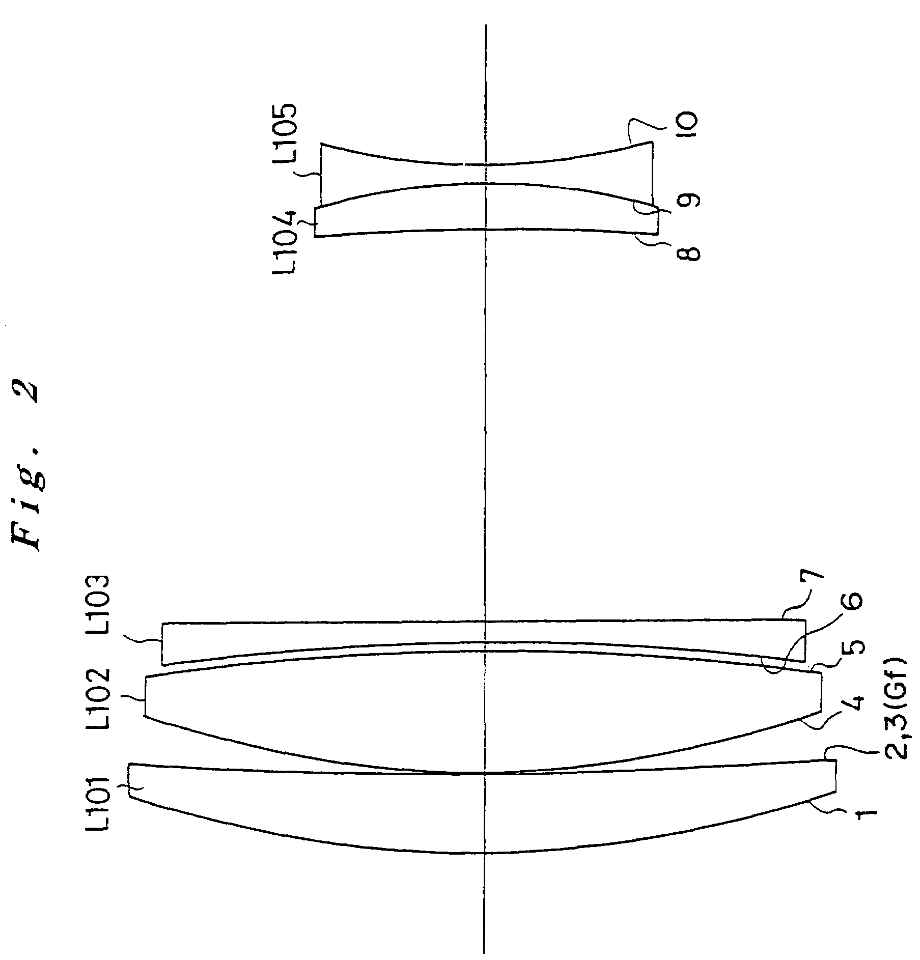
[0063]FIG. 1 is a diagram showing a combined optical system constructed by a front teleconverter lens system combined with an imaging lens according to Example 1 of the present invention. FIG. 2 is a diagram showing the front teleconverter lens system of the combined optical system. FIG. 3 is a diagram showing the imaging lens of the combined optical system. As shown in FIGS. 1 and 3, the imaging lens ML used in the combined optical system according to Example 1 is composed of, in order from an object, a cemented positive lens constructed by a negative meniscus lens L1 having a convex surface facing to the object cemented with a biconvex positive lens L2, a positive meniscus lens L3 having a convex surface facing to the object, a negative meniscus lens L4 having a convex surface facing to the object, a cemented negative lens constructed by a biconcave negative lens L5 cemented with a positive meniscus lens L6 having a convex surface facing to the object, a positive meniscus lens L7 ...

example 2

[0072]FIG. 5 is a diagram showing a combined optical system constructed by a front teleconverter lens system combined with an imaging lens according to Example 2 of the present invention. FIG. 6 is a diagram showing the front teleconverter lens system of the combined optical system. As shown in FIGS. 5 and 6, the front teleconverter lens system TC according to Example 2 is composed of a first lens group FL having positive refractive power and a second lens group RL having negative refractive power. The first lens group FL is composed of a cemented positive lens constructed by, in order from the object, a negative meniscus lens L201 having a convex surface facing to the object cemented with a biconvex positive lens L202 on the image side surface of which a diffractive optical surface is formed. The second lens group RL is composed of a cemented negative lens constructed by, in order from the object, a positive meniscus lens L203 having a concave surface facing to the object cemented ...


PUM


Abstract

A front teleconverter lens system having superb optical performance with less production of aberration in spite of its compactness. The front teleconverter lens system includes, in order from an object, a first lens group having positive refractive power, and a second lens group having negative refractive power, and forming an afocal optical system. A diffractive optical surface is arranged in at least one of the first lens group and the second lens group. The conditional expression 1.2<φF / φR<10 is satisfied, where φF denotes the effective diameter of the most object side lens surface of the first lens group, and φR denotes the effective diameter of the most image side lens surface of the second lens group.

Description

INCORPORATION BY REFERENCE[0001]The disclosures of the following priority applications are herein incorporated by reference:[0002]Japanese Patent Application No. 2002-372479 filed Dec. 24, 2002, and[0003]Japanese Patent Application No. 2003-414150 filed Dec. 12, 2003.BACKGROUND OF THE INVENTION[0004]1. Field of the Invention[0005]The present invention relates to a front teleconverter lens system for varying the focal length of a whole lens system to the longer side by attaching to the object side of an imaging lens.[0006]2. Description of Related Art[0007]A front teleconverter that is attached to the object side of an imaging lens for varying the focal length of the whole lens system to the longer side has been known to be used for a still camera, a video camera, and the like. Generally, this kind of front teleconverter is composed of, in order from the object, a first lens group having positive refractive power, and a second lens group having negative refractive power, where the fo...

Claims


Application Information

Patent Timeline
Patent Type & Authority Patents(United States)
IPC IPC(8): G02B5/18G02B15/12
CPCG02B15/12
Inventor SUZUKI, KENZABURO
Owner NIKON CORP
Learn More