Object recognition apparatus for vehicle, inter-vehicle control apparatus, and distance measurement apparatus

a technology of object recognition and vehicle body, which is applied in the direction of distance measurement, instruments, and using reradiation, etc., can solve the problems of unstable detection of reflected light from the vehicle body, difficulty in high-accuracy vehicle recognition, and insufficient vehicle/non-vehicle decision accuracy, etc., to achieve accurate distance detection

Active Publication Date: 2006-11-14
DENSO CORP
View PDF38 Cites 104 Cited by
  • Summary
  • Abstract
  • Description
  • Claims
  • Application Information

AI Technical Summary

Benefits of technology

[0020]It is therefore an object of the present invention to provide a vehicle object recognition apparatus capable of enhancing the recognition accuracy in utilizing the intensity of reflected light from a reflecting object for recognizing whether the reflecting object is a vehicle or a non-vehicle, an inter-vehicle control apparatus capable of, when the reflecting object is a preceding vehicle, appropriately controlling the inter-vehicle distance to the preceding vehicle through the use of the intensity of the reflected light therefrom, and a distance measurement apparatus capable of making an accurate decision as to whether or not a reflected wave detected is to be used for the distance measurement.
[0021]For this purpose, an object recognition apparatus for a vehicle according to an aspect of the present invention comprises radar means for emitting a plurality of transmission waves throughout a predetermined angular range in each of vertical and horizontal directions of the vehicle to, on the basis of reflected waves thereof, detect distances to reflecting objects, angles in the vertical and horizontal directions and intensities of the reflected waves, decision means for, when a plurality of reflecting objects satisfy a predetermined unity condition, making a decision that the plurality of reflecting objects constitute a unitary reflecting object (same reflecting object), selection means for selecting the highest intensity of intensities of reflected waves corresponding to the reflecting objects decided to be a unitary reflecting object in the decision means, and recognition means for recognizing the reflecting objects on the basis of the distance and the angles in the vertical and horizontal directions which are the detection results acquired by the radar means and for enhancing a probability of a reflecting object being recognized as a non-vehicle when the highest intensity selected by the selection means is below a predetermined reference intensity.
[0022]Thus, in this vehicle object recognition apparatus, when a plurality of transmission waves are emitted and a plurality of reflected waves are received, a decision is first made as to whether or not the reflecting object causing the plurality of reflected waves is a unitary object. If this decision shows the unitary object, the maximum intensity of the intensities of the reflected waves from the reflecting objects constituting the unitary reflecting object is compared with a reference intensity for a discrimination between a vehicle and a non-vehicle. This enables a decision to be univocally made for each unitary reflecting object as to whether the unitary reflecting object is more likely to be a vehicle or a non-vehicle. Moreover, since the decision is made on the basis of the maximum reflected wave intensity from the reflecting objects, for example, even if a portion of a vehicle is made dirty, a precise judgment becomes feasible.

Problems solved by technology

There is a problem which arises with the decision method of the conventional object recognition apparatus, however, in that there is a possibility of the accuracy of the decision on the vehicle / non-vehicle being sufficiently secured.
In this case, if a decision is made that the measurement data on the reflected light having a low light-reception intensity corresponds to a non-vehicle and this measurement data is deleted, the measurement data for the reflecting object to be decided as a vehicle becomes in short supply, which can make it difficult to recognize a vehicle with high accuracy.
However, in the case of the conventional vehicle object recognition apparatus, since, on the basis of only the position (position in a lateral direction, position in a vertical direction and distance) of a reflecting object, a decision is made as to whether or not the reflecting object is a unitary object, the following problems arise.
Therefore, there is a possibility that the detection of the reflected light from the vehicle body becomes unstable and, in this case, the measurement data on the preceding vehicle becomes unstable.
In addition, in the case of a mere decision on a unitary object on the basis of only the position of the reflecting object, there is a threat of separate objects being taken as a unitary object.
In this case, there is a possibility that this object is not correctly recognized as a preceding vehicle because of being different in size from a vehicle.
However, the above-mentioned conventional decision method based on the pulse width of the reflected wave creates the following problems.
However, in the case of the conventional decision method, since the decision as to whether or not the reflected wave is to be used for the distance measurement is made on the basis of the relationship in magnitude between the pulse width (T) of the reflected wave (L) and the deletion pulse width (W), even a reflected wave, which cannot provide a sufficient signal intensity, results in having a pulse width corresponding to a high signal intensity due to the environmental influence such as the spray of water or black smoke, and the distance can be calculated on the basis of the resultant reflected wave (L).

Method used


Image

  • Object recognition apparatus for vehicle, inter-vehicle control apparatus, and distance measurement apparatus
  • Object recognition apparatus for vehicle, inter-vehicle control apparatus, and distance measurement apparatus
  • Object recognition apparatus for vehicle, inter-vehicle control apparatus, and distance measurement apparatus

Examples


first embodiment

(First Embodiment)

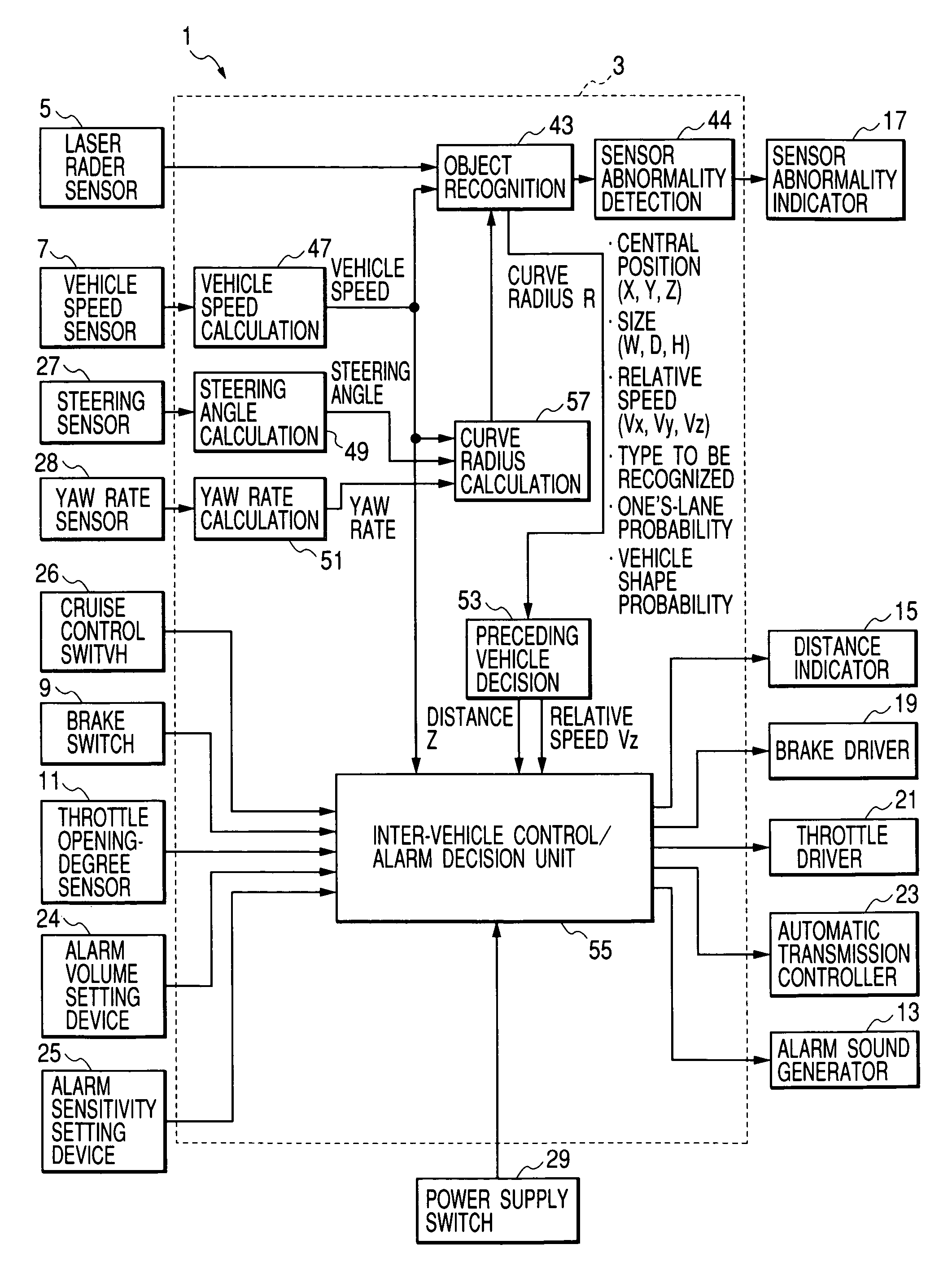
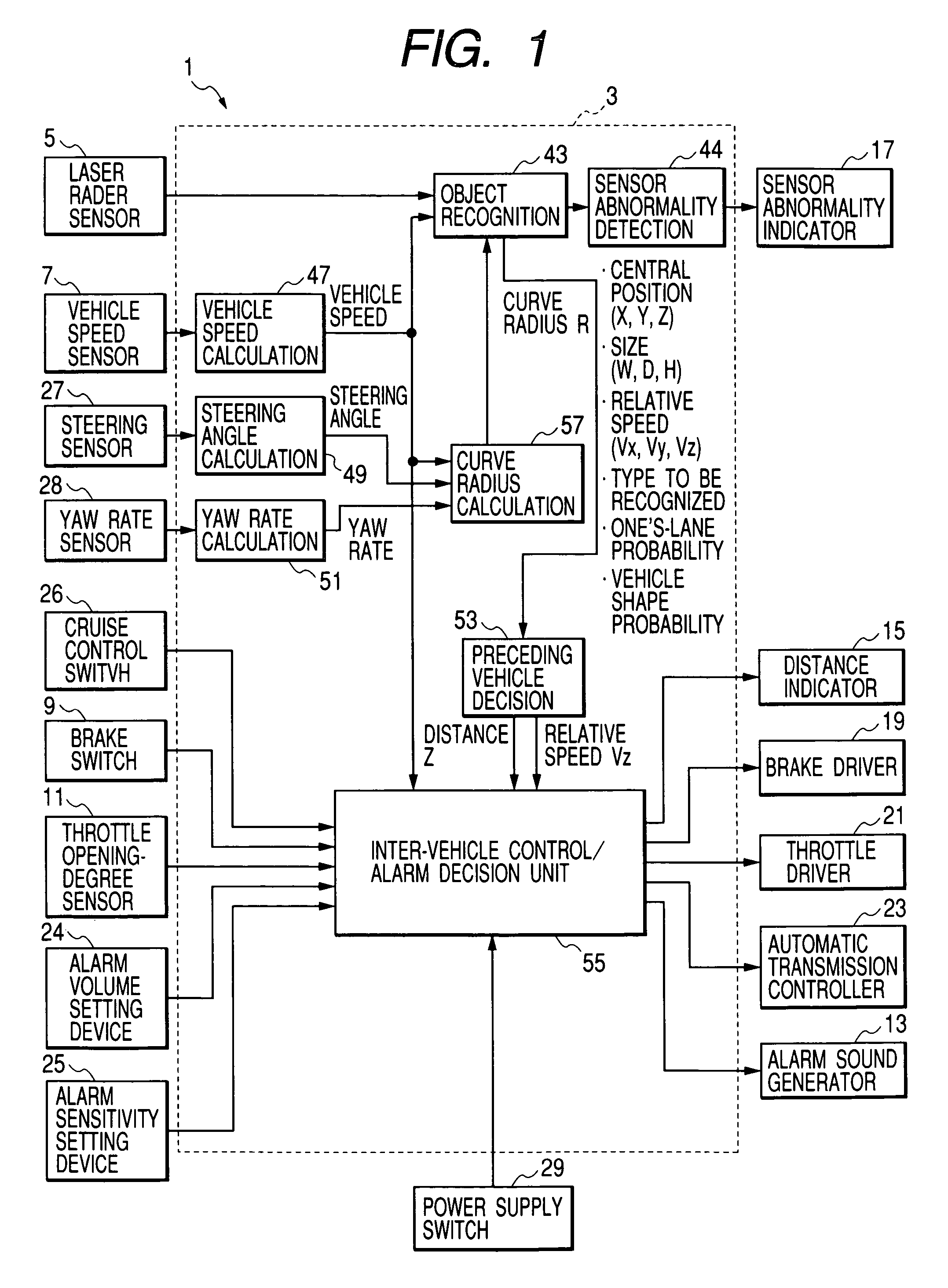
[0106]According to a first embodiment of the present invention, an inter-vehicle control apparatus is equipped with an object recognition apparatus for a vehicle, and the inter-vehicle control apparatus has a function to issue an alarm when an obstacle lies in an alarm zone.

[0107]FIG. 1 is a system block diagram showing the inter-vehicle control apparatus. In the illustration, the inter-vehicle control apparatus, generally designated at reference numeral 1, comprises a recognition / inter-vehicle control ECU 3 as a principal unit. The recognition / inter-vehicle control ECU 3 is composed of a microcomputer acting as a principal component, and is equipped with input / output interfaces (I / O) and various types of drive circuits and various types of detection circuits. This hardware configuration is of a general type, and the description thereof will be omitted for brevity.

[0108]The recognition / inter-vehicle control ECU 3 receives various detection signals from a laser rada...

second embodiment

(Second Embodiment)

[0174]Referring to FIG. 5, a description will be given hereinbelow of processing on object recognition to be implemented in the object recognition block 43 of the recognition / inter-vehicle control ECU 3 according to a second embodiment of the present invention. FIG. 5 is a flow chart showing main processing for the object recognition according to the second embodiment of the present invention.

[0175]In FIG. 5, a step S210 is executed to read the measurement data for each scanning line from the laser radar sensor 5. In the laser radar sensor 5, the measurement cycle for three scanning lines is 100 msec.

[0176]A step S220 follows to delete the data showing a low light-reception intensity. That is, the measurement data includes a pulse width of a stop pulse PB representative of the light-reception intensity of a reflected wave, and the pulse width thereof is compared with a deletion reference value to remove the measurement data showing a pulse width below a predetermi...

third embodiment

(Third Embodiment)

[0215]A distance measurement apparatus according to a third embodiment of the present invention is also applicable to a vehicle control apparatus shown in FIG. 1.

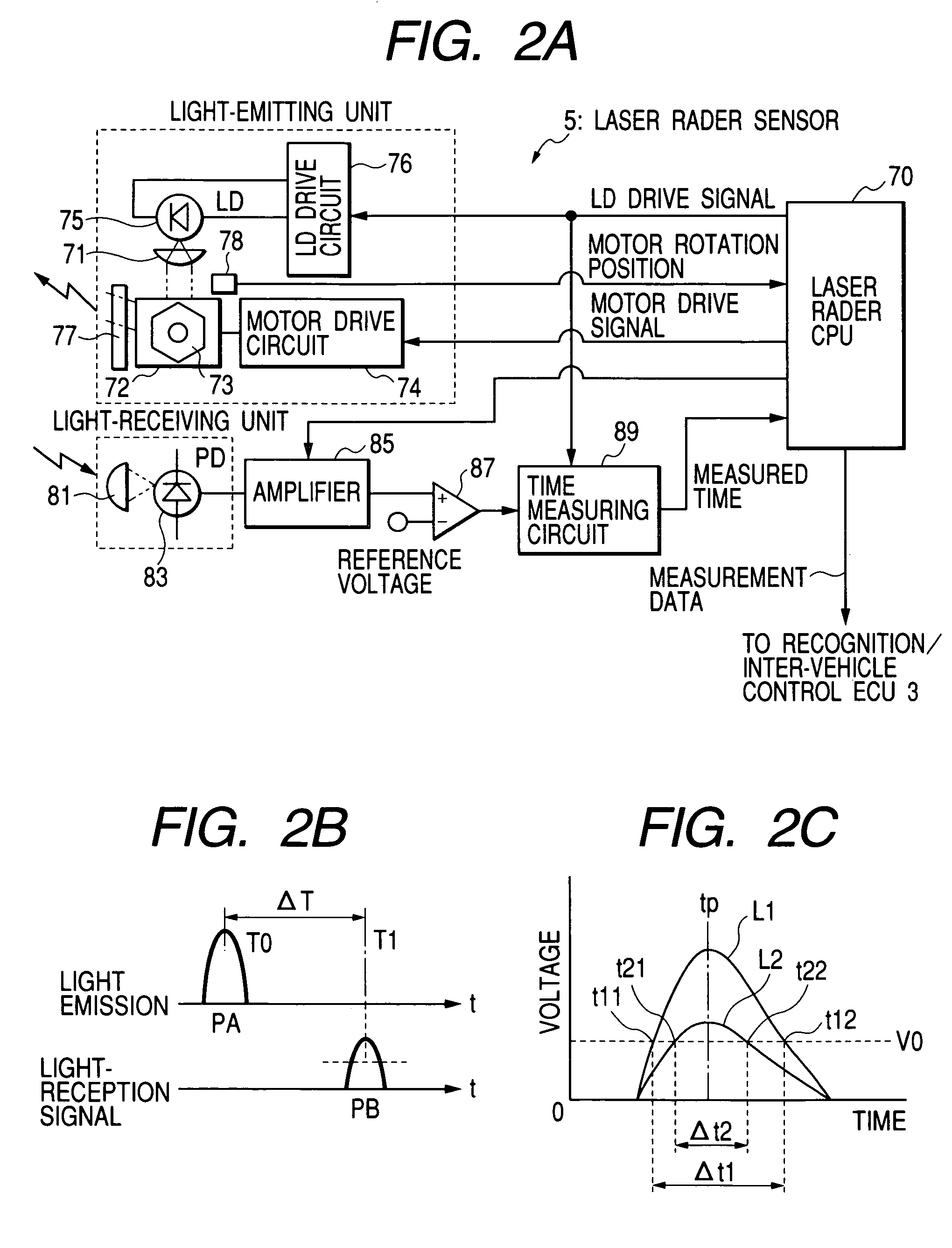
[0216]First of all, referring to FIG. 12, a description will be given hereinbelow of a laser radar sensor 5 of a distance measurement apparatus according to the third embodiment of the present invention. In FIG. 12, the parts corresponding to those in FIG. 2A are marked with the same reference numerals.

[0217]In this embodiment, the laser sensor 5 successively performs the scanning within an area of approximately 7.8 degree in each of right- and left-side directions with respect to a center axis of a vehicle toward the forward direction of the vehicle. Concretely, the scanning is made from the left-side direction to the right-side direction, and 105 transmission laser beams whose horizontal beam numbers are 0 to 104 are emitted at an interval of 0.15 degree. That is, the horizontal beam number 0 corresponds...


PUM


Abstract

In an object recognition apparatus for a vehicle which uses intensities of reflected waves from reflecting objects to make a recognition on whether a reflecting object is a vehicle or a non-vehicle, a plurality of transmission waves are emitted to receive a plurality of reflected waves from the reflecting objects, and a decision is made as to whether or not the reflecting object producing the plurality of reflected waves is a unitary reflecting object. If the decision shows a unitary reflecting object, the highest intensity of intensities of the reflected waves from the unitary reflecting object is compared with a reference intensity to makes a decision on whether the reflecting object is a vehicle or a non-vehicle. This enables univocally making a decision for each unitary reflecting object as to whether the reflecting object is more likely to be a vehicle or to be a non-vehicle, thus improving the recognition accuracy.

Description

BACKGROUND OF THE INVENTION[0001]1) Field of the Invention[0002]The present invention relates to an object recognition apparatus for a vehicle, made to emit (radiate) a plurality of transmission waves throughout a predetermined angular range in vertical and horizontal (lateral or width) directions of the vehicle for recognizing a reflecting object, such as a preceding vehicle (vehicle ahead), existing in a forward direction of one's vehicle (this vehicle) on the basis of reflected waves thereof, and to an inter-vehicle control apparatus designed to control the distance between oneself and the preceding vehicle recognized, and further to a distance measurement apparatus.[0003]2) Description of the Related Art[0004]So far, as exemplified by Japanese Patent Laid-Open No. 2002-40139, there has been proposed an object recognition apparatus which emits a transmission wave(s), such as optical wave or millimetric wave, in a forward direction of one's vehicle to detect the reflected wave for...

Claims


Application Information

Patent Timeline
Patent Type & Authority Patents(United States)
IPC IPC(8): G01C3/00B60T7/22G01S17/931G01S7/48G01S13/931G01S15/931
CPCB60T7/22G01S7/4802G01S17/936B60W2550/10G01S15/931G01S13/931G01S2013/9319G01S2013/93185G01S2013/932G01S2013/93271G01S17/931B60W2554/00B60W2554/804B60W2554/802
Inventor SAMUKAWA, YOSHIENOZAWA, TOYOHITOOHKATA, HIROSHIMATSUOKA, KEIJIHOASHI, YOSHIAKINATSUME, TSUTOMUTERAMURA, EIJI
Owner DENSO CORP
Why Eureka
Try Eureka