Monitoring system for a communications network

Active Publication Date: 2006-11-14
AVAGO TECH INT SALES PTE LTD
View PDF13 Cites 186 Cited by
  • Summary
  • Abstract
  • Description
  • Claims
  • Application Information

AI Technical Summary

Problems solved by technology

Existing in-situ testing methods are either invasive or non-invasive.
PCT/US01/09805), filed Mar. 26, 2001, published Oct. 4, 2001, and entitled “APPARATUS AND METHOD FOR BUILT-IN SELF-TEST OF A DATA COMMUNICATIONS SYSTEM.” A problem with this technique is that it relies on sending and receiving known data, such as pseudorandom bit streams, to measure BER.
Thus, the test is invasive since the normal operation of the communications link is interrupted.
If the received values deviate from the expected values, there are errors.
A problem with this method of measuring BER is that it onl

Method used


Image

  • Monitoring system for a communications network
  • Monitoring system for a communications network
  • Monitoring system for a communications network

Examples


Embodiment Construction

[0022]In the following detailed description of the preferred embodiments, reference is made to the accompanying drawings, which form a part hereof, and in which is shown by way of illustration specific embodiments in which the invention may be practiced. It is to be understood that other embodiments may be utilized and structural or logical changes may be made without departing from the scope of the present invention. The following detailed description, therefore, is not to be taken in a limiting sense, and the scope of the present invention is defined by the appended claims.

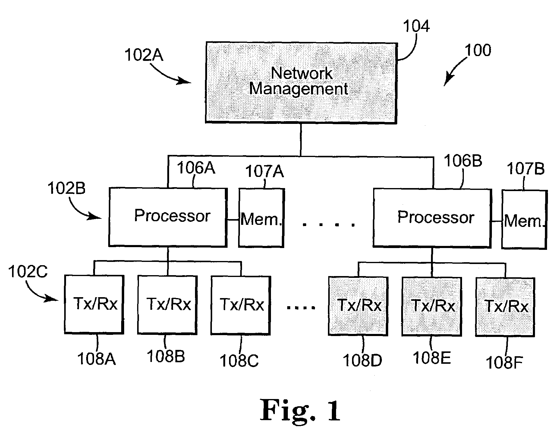
[0023]FIG. 1 is a block diagram illustrating a communications network 100 according to one embodiment of the present invention. In one embodiment, communications network 100 includes non-invasive in-situ self-testing capabilities, as described in further detail below. In one form of the invention, communications network 100 is managed hierarchically, with the hierarchy including a top level 102A, an intermediate...


PUM


Abstract

A monitoring system for a communications network includes a set of components for transmitting and receiving data signals over the communications network. Each component includes a built-in self-test system for performing tests within the component and outputting corresponding test results. Each self-test system is configured to non-invasively determine waveform characteristics of the data signals. The system includes a set of processors. Each processor is coupled to a subset of the set of components, and is configured to evaluate the test results output by the components coupled to the processor. Each processor is configured to detect and predict faults in the communications network based on the evaluation of the test results.

Description

THE FIELD OF THE INVENTION[0001]The present invention generally relates to communications networks, and more particularly to a monitoring system for a communications network.BACKGROUND OF THE INVENTION[0002]Prior art techniques for testing of communications networks generally fall into two categories: in-situ and ex-situ. Existing in-situ testing methods are either invasive or non-invasive. One invasive in-situ technique involves performing a precise bit error ratio (BER) test to assess gross functionality as well as parametric performance. Such a technique is described in International Publication No. WO 01 / 073465 A3 (International Application No. PCT / US01 / 09805), filed Mar. 26, 2001, published Oct. 4, 2001, and entitled “APPARATUS AND METHOD FOR BUILT-IN SELF-TEST OF A DATA COMMUNICATIONS SYSTEM.” A problem with this technique is that it relies on sending and receiving known data, such as pseudorandom bit streams, to measure BER. Thus, the test is invasive since the normal operati...

Claims


Application Information

Patent Timeline
IPC IPC(8): G06F19/00H04B3/46
CPCH04B3/46
Inventor DUCHI, CECELIELSHEIMER, ROBERT
Owner AVAGO TECH INT SALES PTE LTD
Why Eureka
Try Eureka