Recording apparatus

a recording device and a technology for recording mediums, applied in the direction of typewriters, power drive mechanisms, thin material processing, etc., can solve the problems of reducing unable to balance the number of suction ports with the suction capacity of fans, and the roll sheet cannot be sucked reliably, so as to achieve the effect of enhancing the precision of transportation, ensuring constant suction, and high precision

Inactive Publication Date: 2006-11-21
SEIKO EPSON CORP
View PDF18 Cites 22 Cited by
  • Summary
  • Abstract
  • Description
  • Claims
  • Application Information

AI Technical Summary

Benefits of technology

[0012]Further, another object of the invention is, in view of the above problems, to provide a recording apparatus which can control the degree of suction of a recording medium.
[0030]The sucking drag may be calculated based on a size of the recording medium. Moreover, the sucking drag may be calculated based on a property of the recording medium. The property of the recording medium in the present invention includes thickness, material, surface treatment etc. of the recording medium. The size of the recording medium can be also interpreted as one of the properties. Furthermore, the sucking drag may be calculated based on a transportation position of the recording medium. Consequently, it is possible to particularly enhance precision in transportation corresponding to the case in which there is a high possibility that the sucking drag might be changed.

Problems solved by technology

However, in case that many suction ports are provided as described above, the suction capacity of the fans decrease in case the number of the arranged fans is limited and particularly the leading end of the greatly curled roll sheet cannot be sucked reliably.
While reduction of the number of the suction ports resolves this problem, some suction ports are required since the roll sheet is large, so that it is difficult to balance the number of the suction ports with the suction capacity of the fans.
Particularly, in case that the large-sized roll sheet, for example, a wide roll sheet of A0 size or B0 size in JIS (Japanese Industrial Standard) is curved, rising of the roll sheet is easy to be produced on the platen in the printing unit, so that there is fear that printing accuracy cannot be kept.
However, when the roll sheet is curled greatly, it cannot be sucked on the sheet transporting surface by the suction unit.
Further, when the roll sheet has little rigidity and is thin, it is stuck onto the sheet transporting surface by the suction unit.
When the cockling is generated and grown, an interval between the sheet and the recording head becomes nonuniform so that the flight distance of the ink droplet is varied to cause a recording unevenness or the sheet comes in contact with the recording head and is thus contaminated.
In the conventional ink jet printer comprising a sucking type sheet transportation apparatus, a sucking drag to be a transportation resistance of a recording medium which is generated by a suction is changed due to a variation in the area of a sheet covering the hole or a difference in a coefficient of friction for each type of the sheet so that the transportation amount of the sheet is varied, resulting in a deterioration in recording precision in some cases.

Method used


Image

  • Recording apparatus
  • Recording apparatus
  • Recording apparatus

Examples


first embodiment

(First Embodiment)

[0060]First embodiment of the invention will be described below in detail with reference to drawings.

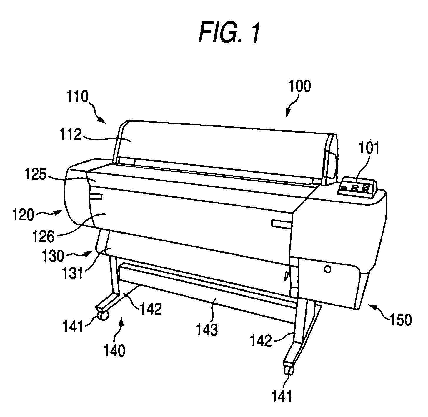
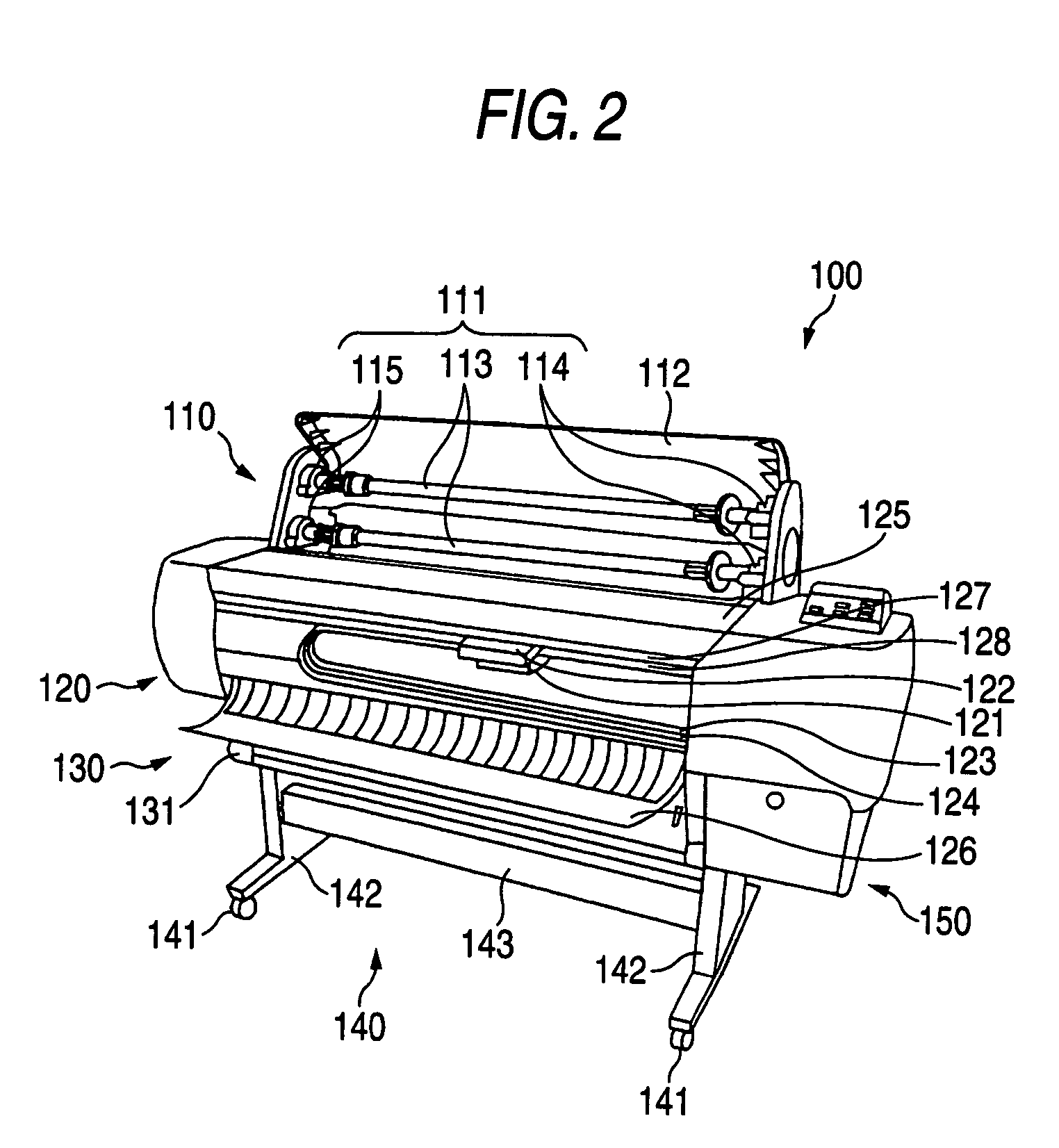
[0061]FIG. 1 is a perspective view showing a constitutional example of an ink jet printer that is a recording apparatus according to the embodiment of the invention, and FIG. 2 is a perspective view showing an example of the inner constitution of a main portion of its ink jet printer. An inkjet printer 100 shown in FIGS. 1 and 2 is a large-sized printer which can print data on a comparatively large-sized printing sheet, for example, a printing sheet of A0 size or B0 size in JIS. In this printer, a sheet feeding portion 110, a printing unit 120, a sheet discharging portion 130 and a leg portion 140 are arranged in this order from the upper part. The printing unit 120 and the sheet discharging portion 130 are integrated as a main body, and the sheet feeding portion 110 and the leg portion 140 are separably constituted.

[0062]The sheet feeding portion 110, as shown in F...

second embodiment

(Second Embodiment)

[0104]FIG. 19 is a sectional view showing a recording medium transportation device according to second embodiment for carrying out the invention. The recording medium transportation device 300 provides a sucking unit 310 sucking and keeping the recording medium at recording and a recording medium transporting mechanism 350 transporting the recording medium to the lower course side from the upper course side of the sucking unit 310. The above sucking unit 310 is arranged at lower side putting a recording medium carriage passage L to the recording head 431 for printing at the recording medium. The sucking unit 310 is formed in hollow box shape of construction of two stages, up and down, consisting of a sucking portion 320 of the upper stage and a sucking force generating portion 330 of the lower stage.

[0105]A sucking portion 320 has a pressure reducing chamber 321 formed in an inner part, a plurality of sucking chambers 323 formed, on a recording medium transporting...


PUM


Abstract

There are provided a suction unit which sucks a recording medium, and a unit which changes sucking force of the suction unit according to the property of the recording medium. Hereby, since the sucking force of the suction unit can be set according to a state of the recording medium. Therefore, for example, even if the recording medium is greatly curled, since its recording medium can be surely sucked on the transporting surface of the recording medium by the suction unit. Further, even if the recording medium has little rigidity and is thin, it is possible to prevent the recording medium from being stuck on the transporting surface of the recording medium by the suction unit.

Description

[0001]The present application is a continuation in part application of U.S. patent application Ser. No. 10 / 041,669 filed on Jan. 10, 2002, now U.S. Pat. No. 6,921,163 which is incorporated herein by reference.BACKGROUND OF THE INVENTION[0002]The present invention relates to a recording apparatus which records data on a recording medium, and particularly to a recording apparatus in which suction of the recording medium is devised.[0003]Generally, in a large-sized printer that is one of conventional recording apparatuses, a sheet feeding portion for feeding a recording medium, for example, printing roll sheet, a printing unit for printing data on the fed roll sheet, and a sheet discharging portion for discharging the printed roll sheet are arranged in this order from the upper part. In case that this large-sized recording apparatus, for example, an ink jet printer is used, a user houses a roll sheet in the sheet feeding portion and pulls out a leading end of the roll sheet. And, the u...

Claims


Application Information

Patent Timeline
Patent Type & Authority Patents(United States)
IPC IPC(8): B41J11/02B41J11/06B41J2/01B41J2/165B41J3/46B41J11/00B41J15/02B41J15/16B65H5/10B65H5/22
CPCB41J3/46B41J11/0025B41J11/003B41J11/0035B41J11/0085B41J11/009B41J11/06B41J15/02B41J15/16B41J29/13B65H5/10B65H5/222
Inventor FUJIOKA, SATOSHIISHII, TAKAYUKISHIMADA, YOSHITAKA
Owner SEIKO EPSON CORP
Why Eureka
Try Eureka