
Pitch-changing system equipped with means for lubricating a load-transfer bearing

a technology of load-transfer bearing and gear changer, which is applied in the direction of pressure lubrication with lubrication pump, propeller, rotor, etc., can solve the problems of sizing the integration of the turbomachine, the complex lubrication of the bearing, and the many difficulties of the turbomachine, so as to achieve compactness.

Active Publication Date: 2021-03-09
SN DETUDE & DE CONSTR DE MOTEURS DAVIATION S N E C M A
View PDF7 Cites 1 Cited by
  • Summary
  • Abstract
  • Description
  • Claims
  • Application Information

AI Technical Summary

Benefits of technology

The invention is about a solution for lubricating a pitch-changing system of a turbomachine. The system includes a mobile body that moves to change the pitch of the turbomachine. The solution includes a first and second telescopic parts that can move with the mobile body and take up the displacement. This allows for lubrication of the load-transfer bearing regardless of the position of the mobile body. The solution also integrates into a cluttered environment without complicating the mounting. The first end of the first part is fixed to a connection ring of the fixed body, which makes the junction between the fixed parts and the mobile parts. The control means is no longer subjected to bending forces, which induced misalignments and harmful leaks. The first part also has at least one first and second vent hole with a central axis, which limits suction phenomena during the displacement of the parts. Overall, the invention simplifies the lubrication of the pitch-changing system and provides better protection against risks.

Problems solved by technology

However, such an architecture involving transforming power coming from the fixed part into a movement on the rotating part of the turbomachine presents many difficulties.
One of the difficulties resides in the sizing of the integration of the various elements in this rotating part.
Indeed, this load-transfer bearing, which is intended to take up the thrust forces of the turbomachine, is displaced in translation and in rotation which makes the lubrication of this bearing complex.
On the other hand, the cylinder is subjected to substantial radial forces of the rotating part that imply deformations of the cylinder as well as problems with the seal, which inevitably are passed on to the means for lubricating said bearing.

Method used


Image

  • Pitch-changing system equipped with means for lubricating a load-transfer bearing
  • Pitch-changing system equipped with means for lubricating a load-transfer bearing
  • Pitch-changing system equipped with means for lubricating a load-transfer bearing

Examples


Embodiment Construction

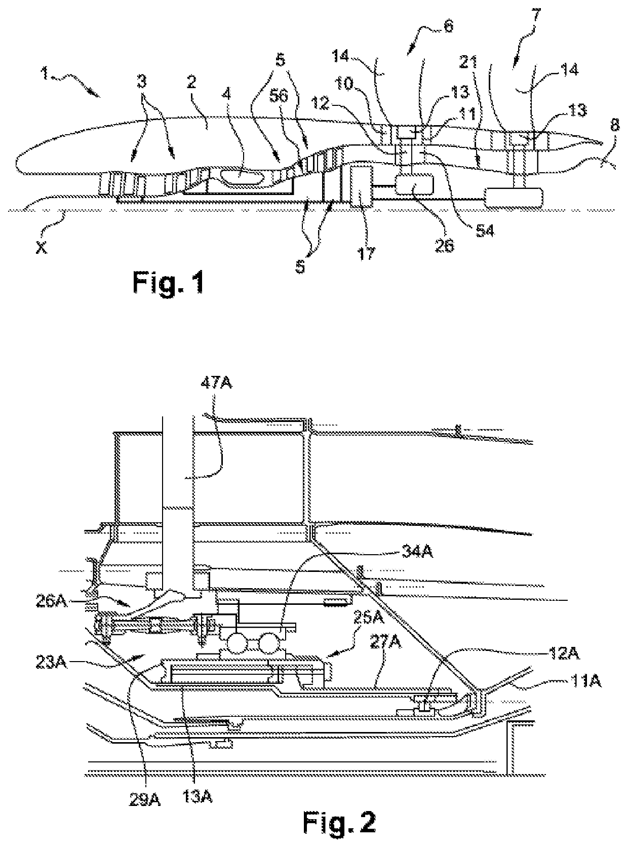
[0049]In FIG. 1 and in the rest of the description is shown a turboprop with a non-streamlined fan with longitudinal axis X intended to be provided on an aircraft. However, the invention can apply to other types of turbomachine.

[0050]The turbomachine 1 comprises a nacelle 2 in which is arranged a gas generator that comprises, from upstream to downstream, a set of compressors 3, a combustion chamber 4 and a set of turbines 5. A nozzle 8 is arranged downstream from the gas generator.

[0051]In this invention, and generally, the terms “upstream” and “downstream” are defined in relation to the circulation of the gases in the turbomachine.

[0052]The set of compressors 3 can include one or two compressor(s) according to the architecture of the simple- or double-stage gas generator. The set of turbines 5 can include a high-pressure turbine and a low-pressure turbine, or two turbines (high pressure and intermediate pressure) and a low-pressure turbine. The gas generator drives the low-pressure...


PUM


Abstract

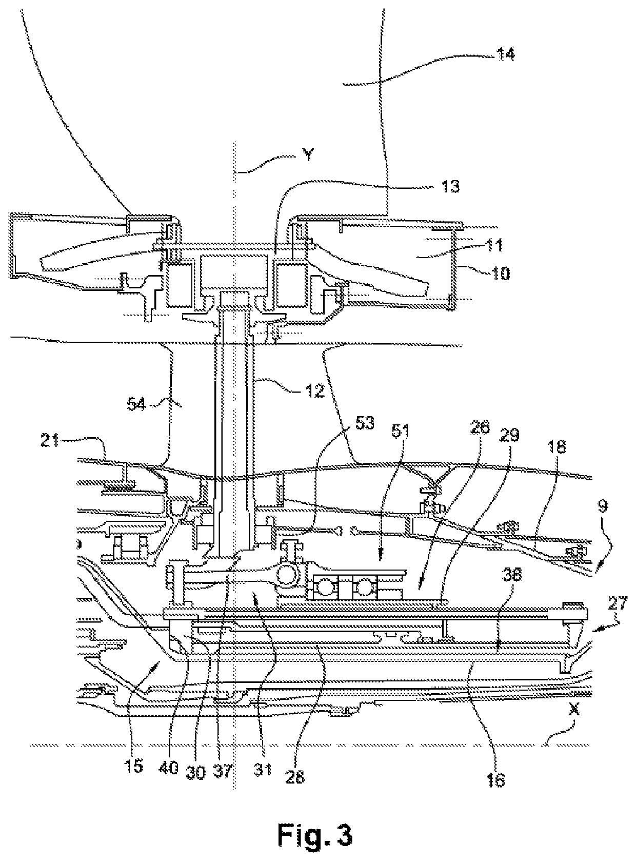
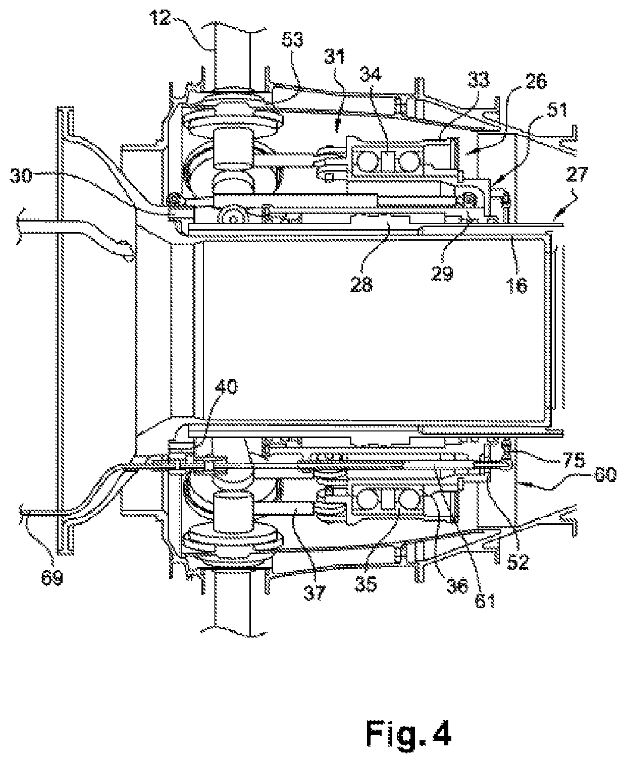
A system for changing the pitch of blades of at least one turbomachine rotor is provided. The system generally includes a control means acting on a connecting mechanism connected to the blades of the rotor and having a body mobile in translation along a longitudinal axis with respect to a fixed body, load-transfer bearing mounted on the mobile body cooperating with the connecting mechanism, and means for lubricating the bearing having a lubricant duct and extending radially above the fixed and mobile bodies. The duct generally includes first and second telescopic tubular parts that slide coaxially with respect to one another, the first part connected to the fixed body and the second part connected to the mobile body, and means for spraying lubricant into the bearing mounted on the mobile body and lubricant supply conduit mounted on the mobile body to connect the duct to the spraying means.

Description

1. FIELD OF THE INVENTION[0001]This invention relates to the field of aeronautical propulsion. It relates to a system for changing the pitch of blades of a propeller driven by a turbomachine and in particular means for lubricating a load-transfer bearing of said pitch-changing system.2. PRIOR ART[0002]The change in pitch or variable timing of blades of a turbomachine propeller is one of the ways to improve the performance and output of turbomachines in different flight conditions.[0003]Turbomachines are known, such as propulsion propeller doublet of a turboprop, for example counter-rotating, referred to as “open rotor” and “unducted fan” provided with these pitch-changing systems. Turboprop are distinguished from turbojets by the use of a propeller outside of the nacelle (non-streamlined) instead of a fan. The pitch-changing system can also apply to a turboprop with a propulsion propeller or be suitable indifferently to one or each propeller.[0004]In a turbine engine of the open rot...

Claims


Application Information

Patent Timeline
Patent Type & Authority Patents(United States)
IPC IPC(8): B64C11/38F01D25/16F01D25/20F01D7/00F01M1/02B64C11/30F02K3/062
CPCB64C11/38F01D7/00F01D25/16F01D25/20F01M1/02B64C11/306F02K3/062B64C11/303F01D25/18
Inventor SERVANT, RÉGIS EUGÈNE HENRILAFITTE, ANTHONYSOURYAVONGSA, EDDY KEOMORAKOTTTAJAN, SÉBASTIEN EMILE PHILIPPEMARTIN, ARNAUD
Owner SN DETUDE & DE CONSTR DE MOTEURS DAVIATION S N E C M A
Learn More