Fuel supply device and method for producing same

a technology of fuel supply and fuel feeder, which is applied in the direction of liquid fuel feeder, machine/engine, transportation and packaging, etc., can solve the problems of deterioration of fuel supply stability and achieve the effect of high stability

Active Publication Date: 2020-09-08
AISAN IND CO LTD
View PDF13 Cites 1 Cited by
  • Summary
  • Abstract
  • Description
  • Claims
  • Application Information

AI Technical Summary

Benefits of technology

[0007]The present disclosure is made in view of the above disadvantage, and it is an objective of the present disclosure to provide a fuel supply device, which has a high stability with respect to fuel supply, and a method for producing the fuel supply device.
[0016]According to the first aspect of the present disclosure, the fuel recovery passage portion includes the excess fuel outlet that discharges the excess fuel and is located on the inner side of the opening where the inside of the sub-tank is placed. With the excess fuel outlet discussed above, it is possible to limit scattering of the excess fuel, which is discharged from the fuel pump toward the outside of the fuel tank and becomes excess at the pressure-regulation path, at the outside of the sub-tank, and thereby it is possible to efficiently recover the excess fuel into the inside of the sub-tank. In addition, the discharge of the excess fuel from the excess fuel outlet is implemented in the state where the fuel recovery passage portion is inserted into the opening from the outside of the sub-tank while the gap is formed between the excess fuel outlet and the opening. Therefore, even when the vapor contained in the excess fuel is discharged into the inside of the sub-tank, it is possible to expel the vapor to the outside of the sub-tank through the gap. Specifically, it is possible to limit the suctioning of the vapor into the fuel pump through the suction filter. Therefore, it is possible to provide the fuel supply device that has the high stability with respect to the fuel supply.
[0027]According to the second aspect of the present disclosure, the unit, which includes the regulator holder, is assembled to the sub-tank in the direction that coincides with the opening direction of the opening. In this way, the fuel recovery passage portion is inserted such that the excess fuel outlet is inserted from the outside of the sub-tank into the inside of the sub-tank through the opening. The placement of the pressure regulator relative to the sub-tank and the placement of the excess fuel outlet relative to the sub-tank can be implemented by the assembling in the single direction. Therefore, the fuel supply device, which has the high stability with respect to the fuel supply, can be easily provided.

Problems solved by technology

When this vapor is suctioned into the fuel pump through the suction filter once again, the fuel supply stability is deteriorated.

Method used


Image

  • Fuel supply device and method for producing same
  • Fuel supply device and method for producing same
  • Fuel supply device and method for producing same

Examples


first embodiment

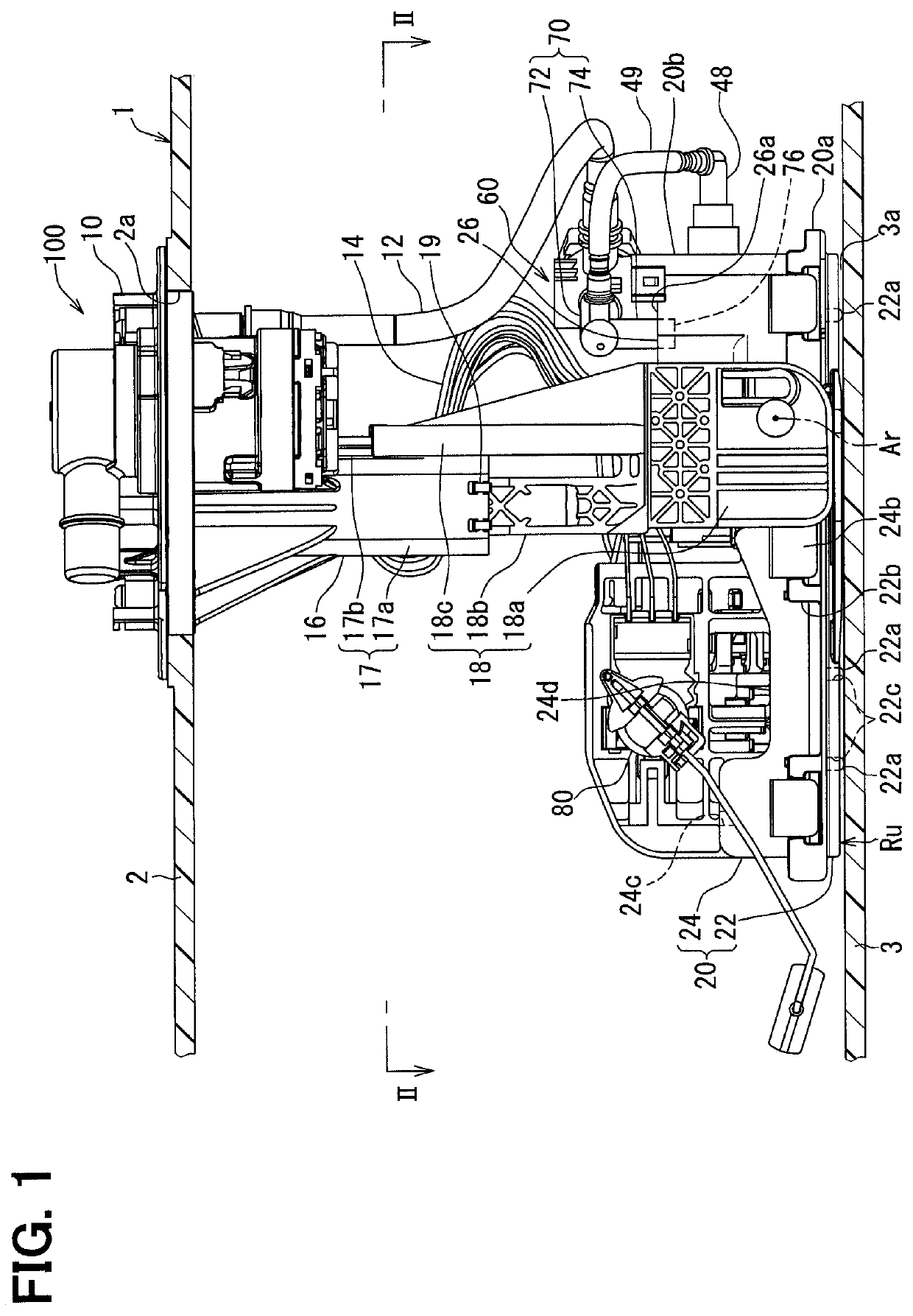
[0042]As shown in FIG. 1, a fuel supply device 100 according to a first embodiment of the present disclosure is installed in a fuel tank 1 of a vehicle and is applied to an internal combustion engine of the vehicle. The fuel supply device 100 supplies fuel stored in the fuel tank 1 to the internal combustion engine located at an outside of the fuel tank 1. Here, the fuel tank 1 is made of resin or metal and is shaped into a hollow form. An insertion hole 2a extends through an upper wall 2 of the fuel tank 1. The fuel supply device 100 is inserted into an inside of the fuel tank 1 through the insertion hole 2a. Under the above-described inserted state, the internal combustion engine, which is a supply destination of the fuel from the fuel supply device 100, may be a gasoline engine or a diesel engine. A top-to-bottom direction and a transverse(s) direction of FIG. 1, which shows an installed state of the fuel supply device 100 in the fuel tank 1, substantially coincide with a vertica...

second embodiment

[0078]As shown in FIG. 10, a second embodiment of the present disclosure is a modification of the first embodiment. The second embodiment will be described mainly with respect to differences relative to the first embodiment.

[0079]The sub-tank 220 of the second embodiment includes a receiving portion 225 that projects from a peripheral wall 224a of the sub-tank 220, which is formed as a part of the upper cover member 224, into the inside of the sub-tank 220. The receiving portion 225 is placed between the excess fuel outlet 76 and the suction filter 30 and thereby receives the excess fuel, which is discharged and is dropped from the excess fuel outlet 76.

[0080]Specifically, the receiving portion 225 of the second embodiment is formed integrally with the upper cover member 224 in one piece from resin such that the receiving portion 225 is in a form of a thin wall. The receiving portion 225 includes a tilt wall part 225a and a distal end wall part 225b. The tilt wall part 225a is joine...

third embodiment

[0083]As shown in FIG. 11, a third embodiment of the present disclosure is a modification of the first embodiment. The third embodiment will be described mainly with respect to differences relative to the first embodiment.

[0084]In the sub-tank 320 of the third embodiment, the opening 26 is located at the ceiling portion 20b of the sub-tank 320 and is formed at the upper cover member 324.

[0085]However, the upper inflow hole 24c is not formed at the sub-tank 320 of the third embodiment unlike the first embodiment. Therefore, in the ceiling portion 20b, there is no communicating part, which communicates between the inside and the outside of the sub-tank 320, except the gap 26a that is formed between the opening 26 and the fuel recovery passage portion 70.

[0086]Furthermore, unlike the first embodiment, the recess 24d is not formed at the upper cover member 324 unlike the first embodiment. Therefore, the upper cover member 324 includes: a flat portion 328, which has the cover height Hc, ...


PUM


Abstract

In a fuel tank, a pressure regulator is placed at an outside of a sub-tank and regulates a pressure of fuel of a pressure-regulation path, which is discharged from a fuel pump and is fed toward an outside of the fuel tank. A fuel recovery passage portion recovers excess fuel, which becomes excess at the pressure-regulation path, to the sub-tank. The sub-tank has an opening at a location that is higher than the suction filter. The fuel recovery passage portion is inserted from the outside of the sub-tank into the inside of the sub-tank through the opening while a gap is formed between the fuel recovery passage portion and the opening, so that the fuel recovery passage portion has an excess fuel outlet that discharges the excess fuel at a location that is on an inner side of the opening where an inside of the sub-tank is placed.

Description

CROSS REFERENCE TO RELATED APPLICATION[0001]This application is the U.S. national phase of International Application No. PCT / JP2017 / 006969 filed Feb. 24, 2017, which designated the U.S. and claims priority to Japanese Patent Application No. 2016-55978 filed on Mar. 18, 2016, the entire contents of each of which are hereby incorporated by reference.TECHNICAL FIELD[0002]The present disclosure relates to a fuel supply device that is configured to supply fuel from an inside of a fuel tank of a vehicle to an outside of the fuel tank.BACKGROUND ART[0003]Previously, there is known a fuel supply device that is configured to supply fuel from an inside of a fuel tank of a vehicle to an outside of the fuel tank. The device, which is disclosed in the patent literature 1, includes a sub-tank, a suction filter, a fuel pump, a pressure regulator and a fuel recovery passage portion. The sub-tank stores the fuel. The fuel pump suctions the fuel, which is filtered through the suction filter placed al...

Claims


Application Information

Patent Timeline
Patent Type & Authority Patents(United States)
IPC IPC(8): B60K15/03F02M37/22F02M37/20B60K15/035B60K15/01F02M37/50F02M37/00F02M37/10
CPCF02M37/20F02M37/0029B60K15/035B60K15/03F02M37/106F02M37/22F02M37/50F02M37/0052B60K15/01B60K2015/03243B60K2015/03542B60K2015/03523B60K2015/03236B60K2015/03296
Inventor ADACHI, RUIKOBAYASHI, KIYOMORIHAYASHI, NORIHIRO
Owner AISAN IND CO LTD
Why Eureka
Try Eureka