Liquid ejecting head and liquid ejecting apparatus

a technology of liquid ejecting head and liquid ejecting apparatus, which is applied in the direction of electrical apparatus, piezoelectric/electrostrictive/magnetostrictive devices, printing, etc., can solve the problems of ejection characteristic change, pressure fluctuation, and moisture entering the accommodation space of the driving element, so as to reduce the character deterioration of the driving element caused by dew condensation, enhance the hygroscopic effect of the moisture absorbent, and reduce condensation

Active Publication Date: 2020-05-19
SEIKO EPSON CORP
View PDF30 Cites 0 Cited by
  • Summary
  • Abstract
  • Description
  • Claims
  • Application Information

AI Technical Summary

Benefits of technology

[0005]An advantage of some aspects of the invention is that the driving element is protected from the moisture while the pressure fluctuation in the space that accommodates the driving element is suppressed.
[0006]According to an aspect of the invention, there is provided a liquid ejecting head that includes a plurality of driving elements that causes a liquid to be ejected from a nozzle by fluctuating a pressure, a sealing body that forms a first space for accommodating the plurality of driving elements, a case member that forms a second space for surrounding the sealing body, an atmosphere vent that is formed in the case member and through which the second space communicates with atmosphere, a communication hole that is formed in the sealing body and through which the first space communicates with the second space, and a moisture absorbent in the second space. With this configuration, since the first space for accommodating the driving element communicates through a communication hole with the second space that communicates with atmosphere, the first space can be prevented from becoming a sealed space. Therefore, the fluctuation of the pressure in the accommodation space caused by the vibration of the pressure chamber can be suppressed. Further, since the moisture absorbent is disposed in the second space, even if the moisture enters the second space from the atmosphere vent, the moisture is absorbed by the moisture absorbent in the second space. Therefore, since the moisture entering the first space through the communication hole can be reduced, the driving element can be protected from moisture. With this configuration, the driving element can be protected from the moisture while the pressure fluctuation of the space for accommodating the driving element is suppressed.
[0007]In the liquid ejecting head, the moisture absorbent may be in a position closer to the communication hole than to the atmosphere vent. With this configuration, since the moisture absorbent is in a position closer to the communication hole than to the atmosphere vent, compared with a case where the moisture absorbent is in a position close to the atmosphere vent, it is possible to suppress suction of the moisture outside the second space from the atmosphere vent and absorption of the moisture. Therefore, the time during which hygroscopic capacity of the moisture absorbent can be maintained can be extended. Further, since the moisture absorbent is in a position close to the communication hole, compared with a case where the moisture absorbent is in a position away from the communication hole, it is possible to make it difficult for the moisture to enter from the communication hole.

Problems solved by technology

However, since the adhesive escape space portion communicates with the air, there is a concern that the moisture enters the accommodation space of the driving element from the adhesive escape space portion.
However, if the atmosphere communication path that communicates with the accommodation space of the driving element is closed as in JP-A-2016-000500, the accommodation space of the driving element becomes a sealed space, so that a vibration of the pressure chamber caused by driving of the driving element is propagated to the accommodation space of the driving element, and a pressure fluctuation occurs in the accommodation space of the driving element as well.
Since each pressure chamber is also affected by the pressure fluctuation of the accommodation space of the driving element, there is a concern that an ejection characteristic changes due to the pressure fluctuation of the accommodation space of the driving element.
Therefore, there is a concern that the ejection characteristic changes depending on the number of the driving elements to be driven.
Further, since the moisture absorbent is in a position close to the communication hole, compared with a case where the moisture absorbent is in a position away from the communication hole, it is possible to make it difficult for the moisture to enter from the communication hole.
Then, there is a concern that the dew condensation droplet evaporates and the moisture increases when a temperature rises again thereafter.
Therefore, since the moisture of the first space can be lowered, the dew condensation can be made difficult in the first space.
With this configuration, since the minimum opening area of the communication hole is smaller than the minimum opening area of the atmosphere vent, it is difficult for the moisture that entered the second space from the atmosphere vent to enter the first space from the communication hole.

Method used


Image

  • Liquid ejecting head and liquid ejecting apparatus
  • Liquid ejecting head and liquid ejecting apparatus
  • Liquid ejecting head and liquid ejecting apparatus

Examples


first embodiment

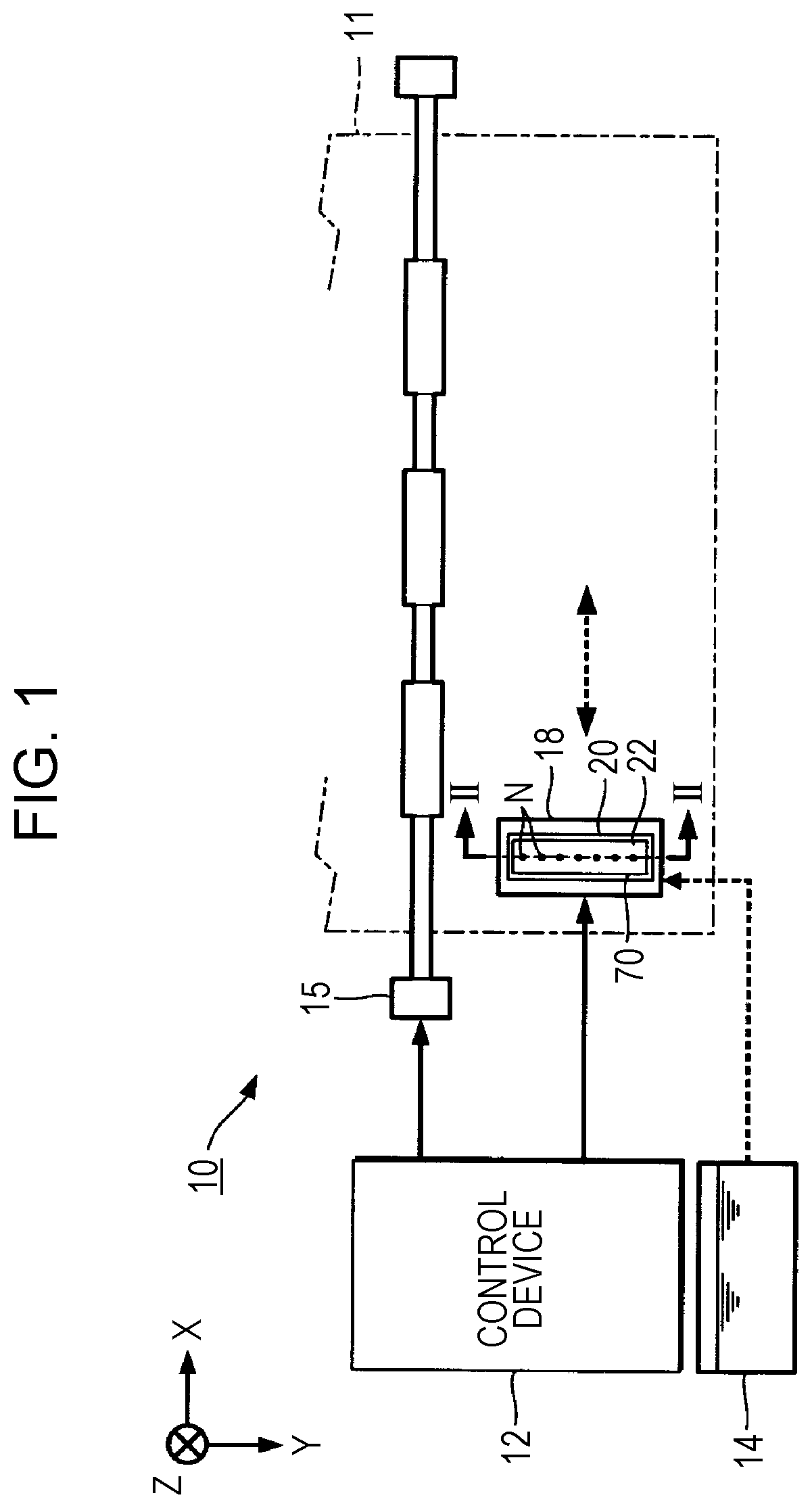
[0025]FIG. 1 shows a first embodiment of the invention, in which a partial configuration of the liquid ejecting apparatus 10 is illustrated. The liquid ejecting apparatus 10 of the first embodiment is an ink jet type printing apparatus that ejects ink, an example of a liquid, onto a medium 11 such as printing paper and the like. The liquid ejecting apparatus 10 shown in FIG. 1 includes a control device (controller) 12, a transport mechanism 15, a carriage 18, and a liquid ejecting head 20. A liquid container 14 that stores ink is mounted on the liquid ejecting apparatus 10.

[0026]The liquid container 14 is an ink tank type cartridge made of a box-shaped container attachable to and detachable from the main body of the liquid ejecting apparatus 10. The liquid container 14 is not limited to a box-shaped container and may be an ink pack type cartridge made of a sack-shaped container. In the liquid container 14, ink is stored. The ink may be black ink or may be color ink. The ink stored i...

second embodiment

[0052]A second embodiment of the invention will be described. For the element that has the same operation and function as in the first embodiment in each form presented below, reference numerals used in the description of the first embodiment will be used and the detailed description thereof will be omitted as deemed appropriate. In the second embodiment, the liquid ejecting head 20 that includes a plurality of the liquid ejection sections 70 will be presented as an example.

[0053]FIG. 7 shows a sectional view of the configuration of liquid ejecting head 20 according to the second embodiment and corresponds to FIG. 2. The liquid ejecting head 20 of FIG. 7 includes the two liquid ejection sections 70 in the second space S2. In FIG. 7, a case where the two liquid ejection sections 70 are arranged side by side in the Y-direction is presented as an example, but a plurality of the liquid ejection sections 70 may be arranged in a zigzag manner. The communication hole 784 of FIG. 7 is provi...

modification example

[0055]The aspects and the embodiments described above can be modified variously. Specific modifications of aspects are presented below. Two or more aspects randomly selected from the aspects presented below and described above can be properly merged within a scope where the aspects do not contradict one another.

[0056](1) In the embodiment described above, a serial head that causes the carriage 18 on which the liquid ejecting head 20 is mounted to reciprocate repeatedly in X-direction is presented as an example. However, the invention is also applicable to a line head in which the liquid ejecting heads 20 are arranged over the entire width of medium 11.

[0057](2) In the embodiment described above, the liquid ejecting head 20 of the piezoelectric type using the piezoelectric element that applies a mechanical vibration to the pressure chamber is presented as an example. However, it is also possible to adopt a thermal type liquid ejecting head using a heat generating element that generat...


PUM


Abstract

A liquid ejecting head includes a plurality of driving elements that causes an ejection of a liquid from a nozzle by causing a fluctuation in a pressure, a sealing body that seals a first space for accommodating the plurality of driving elements, a case member that forms a second space for surrounding the sealing body, an atmosphere vent that is formed in the case member and through which the second space communicates with the air, a communication hole that is formed in the sealing body and through which the first space communicates with the second space, and a moisture absorbent disposed in the second space.

Description

CROSS REFERENCE TO RELATED APPLICATIONS[0001]This application claims priority to Japanese Patent Application No. 2017-250936 filed on Dec. 27, 2017. The entire disclosure of Japanese Patent Application No. 2017-250936 is incorporated herein by reference.BACKGROUND1. Technical Field[0002]The present invention relates to a technique for ejecting a liquid such as ink.2. Related Art[0003]In a liquid ejecting head that includes a plurality of liquid ejection sections that eject a liquid by changing a pressure of a pressure chamber filled with a liquid such as ink with a driving element such as a piezoelectric element, a space in which the driving element is accommodated is sealed to protect the driving element from moisture. For example, in JP-A-2016-000500, an accommodation space of the driving element is sealed by bonding a sealing plate with an adhesive to a substrate on which the accommodation space of the driving element is formed. The adhesive that protrudes during such a bonding i...

Claims


Application Information

Patent Timeline
Patent Type & Authority Patents(United States)
IPC IPC(8): B41J2/045B41J29/377B41J29/02B41J2/14H01L41/053H01L41/09
CPCB41J29/02B41J29/377B41J2/14201B41J2/04581B41J2/14233H01L41/0533B41J2002/14241H01L41/0973B41J2/14H10N30/883H10N30/2047
Inventor NAKAJIMA, YOSHINORIKANEGAE, TAKAHIROOWAKI, HIROSHIGEOTSUKI, MAKOTOMATSUOKA, HIRONORI
Owner SEIKO EPSON CORP
Why Eureka
Try Eureka