Right angle drill with an improved structure for accommodating a light assembly

a right angle drill and assembly technology, applied in the field of angle drills, can solve the problems of restricting the installation position, hindering the removal of the field system, and reducing the utility of the devi

Inactive Publication Date: 2006-11-21
MAKITA CORP
View PDF13 Cites 48 Cited by
  • Summary
  • Abstract
  • Description
  • Claims
  • Application Information

AI Technical Summary

Benefits of technology

[0008]In view of the above-identified problems, an important object of the present invention is to provide an angle drill which incorporates an illuminant that does not adversely affect the locations, installation, or removal of the motor and related parts.
[0009]The above object and other related objects are realized by the invention, which provides an angle drill including: a motor; a generally cylindrical motor housing which has a center axis and defines therein a hole for accommodating the motor; a top housing coupled to one end of the motor housing; a spindle extending, at a right angle with respect to the center axis of the motor housing, inside the top housing to one end which protrudes from the top housing; at least one illuminant disposed on a peripheral surface of the motor housing for illuminating objects generally located in the direction in which the spindle protrudes; and a first protrusion which is disposed on the peripheral surface of the motor housing and located on the same side of a plane containing the center axis as the protruding end of the spindle. The first protrusion is located outside the motor accommodating hole, and the at least one illuminant is disposed within the first protrusion. This arrangement ensures that the at least one illuminant does not limit the location of installation of the motor or obstruct the removal or installation of the motor for repair or replacement of the motor. The illuminant, being disposed within the protrusion, can effectively throw light on the location of work by ensuring the user's hand does not block the light path.
[0010]According to one aspect of the present invention, the angle drill further includes a switch for activating the motor by its depression toward the motor housing. The switch protrudes from the peripheral surface of the motor housing generally in parallel with the spindle, and the first protrusion extends axially farther outwards from the motor housing than does the switch. This arrangement prevents inadvertent activation of the switch when the user places the angle drill on a flat surface with the switch face-down.
[0011]According to one aspect of the present invention, the first protrusion is adapted so as to be removably attached to the motor housing. In this way, an angle drill without an illuminant can use the same motor housing by replacing the protrusion without any redesign of the motor housing required. This arrangement advantageously reduces the overall manufacturing costs of the power tool.
[0012]According to another aspect of the present invention, the motor housing includes therein a cut-out including on opposing side surfaces thereof a pair of ridges which are spaced apart from each other by a predetermined distance. Moreover, the drill further includes a light unit which in turn includes a plate portion having an inner surface with substantially the same curvature as an inner surface of the accommodating hole. The light unit further includes the first protrusion on an outer surface of the plate portion, and a pair of grooves in opposing side surfaces thereof. The grooves are spaced apart by approximately the predetermined distance and complementary in shape to the ridges on the cut-out of the motor housing so as to permit removable attachment of the light unit to the cut-out by slidable engagement of the ridges and the grooves. Thus, upon attachment of the light unit to the cut-out, the inner surfaces of the plate portion and the motor housing provide smooth transition therebetween within the motor accommodating hole, with the plate portion not protruding into the motor accommodating hole.

Problems solved by technology

While achieving its intended objective, the forgoing conventional arrangement suffers from a number of deficiencies that reduce the utility of the device.
For example, as the illuminant or light unit protrudes into the motor accommodating hole of the motor housing, the illuminant may restrict the installation position of the motor's field system within the motor accommodating hole.
The illuminant may additionally hinder the removal of the field system from the motor housing during repair or servicing.
Moreover, the motor housing must be reshaped depending on the presence or absence of the illuminant in the tool, thus increasing the manufacturing and other related costs of the drill.

Method used


Image

  • Right angle drill with an improved structure for accommodating a light assembly
  • Right angle drill with an improved structure for accommodating a light assembly
  • Right angle drill with an improved structure for accommodating a light assembly

Examples


Embodiment Construction

[0026]A preferred embodiment of the present invention will be described hereinafter with reference to the attached drawings.

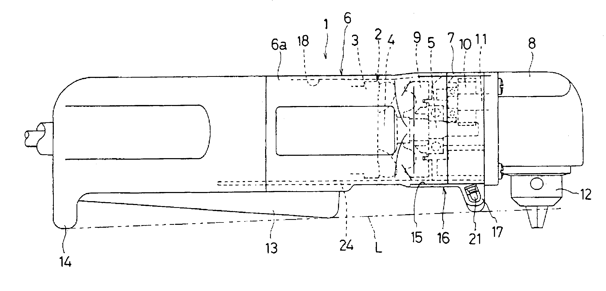
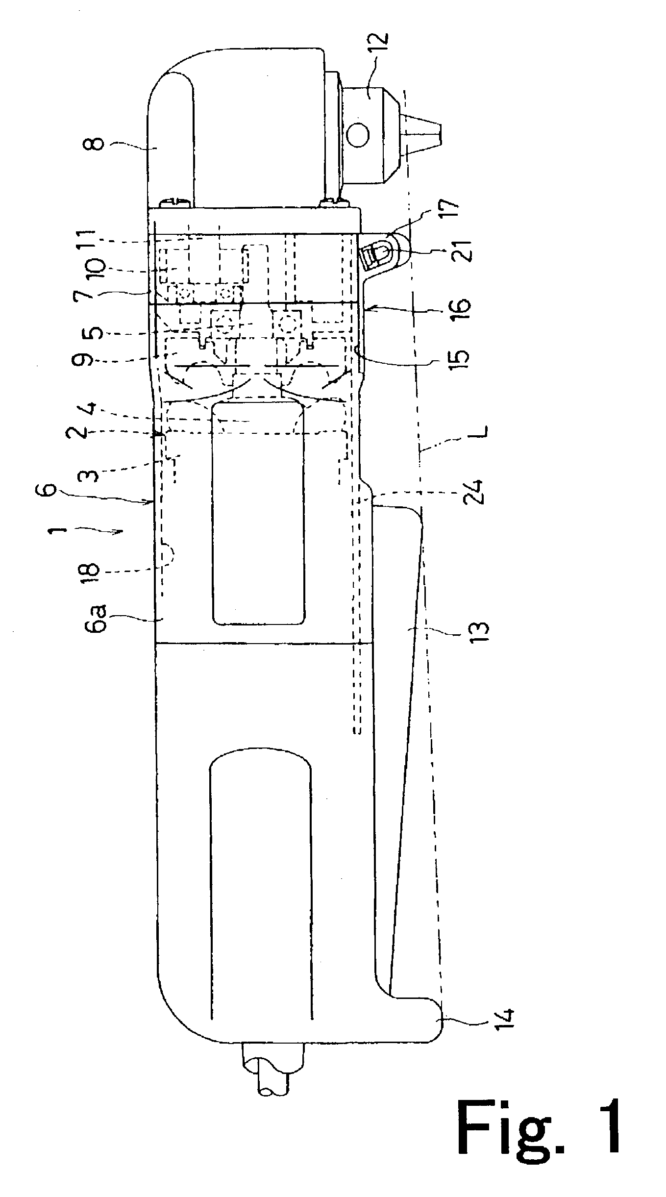
[0027]FIG. 1 is a side elevation of a right angle drill 1 in accordance with the present invention, with part of its internal mechanisms shown in broken lines. The right angle drill 1 includes a motor housing 6 which in turn includes a cylindrical main housing body 6a and a gear housing cover 7 (described below) The main housing body 6a encases an electric motor 2 including a field system 3 and an armature 4 with an output shaft 5. The main housing body 6a defines therein a hole or cavity 18 for accommodating the motor 2. The above-mentioned gear housing cover 7 is assembled to the front end (the right side in the drawing) of the main housing body 6a so as to form the motor housing 6. The gear housing cover 7 rotatably supports the output shaft 5 of the armature 4 therein. A top housing or gear housing 8 is screwed to the front end of the main housing body 6a, ...


PUM

PropertyMeasurementUnit
angleaaaaaaaaaa
distanceaaaaaaaaaa
shapeaaaaaaaaaa

Abstract

A right angle drill (1) includes a motor housing (6) which defines therein a hole (18) for accommodating a motor field system (3), a cut-out (15) formed in the underside of the motor housing (6) from the front end toward the rear of the tool (1), and a light unit (16) slidably fitted in the cut-out (15). The light unit (16) is a plate member having an arcuate cross section so as to define an inwardly curved rear (i.e., inner) surface (16a) along its entire length. The unit's inner surface (16a) conforms to the inner surface of the accommodating hole (18) of the motor housing (6). The light unit (16) additionally includes a protrusion (17) at the front outer surface thereof. Furthermore, the protrusion (17) contains a pair of LEDs (21) for illuminating objects below an output spindle (12) to which a bit can be attached.

Description

RELATED APPLICATION(S)[0001]This application claims priority on Japanese Patent Application No. 2002-28679 filed on Feb. 5, 2002.BACKGROUND OF THE INVENTION[0002]1. Field of the Invention[0003]The present invention generally relates to electric power tools. More particularly, the present invention relates to an angle drill which includes a cylindrical motor housing and a top housing which is coupled to an end of the motor housing and from which a spindle protrudes at a right angle with respect to the motor housing.[0004]2. Description of the Related Art[0005]Certain known angle drills include a cylindrical motor housing which defines therein a hole to accommodate a motor and a top housing coupled to the forward end of the motor housing. The angle drill further includes an output spindle extends inside and out of the top housing at a right angle with respect to the motor housing. Additionally included in a certain type of angle drill is one or more illuminants (such as light emitting...

Claims


Application Information

Patent Timeline
Patent Type & Authority Patents(United States)
IPC IPC(8): B23B45/00B25F5/02
CPCB25F5/021Y10T408/21Y10T408/65
Inventor HARA, AKIHITOSHIMIZU, SHINYA
Owner MAKITA CORP
Why Eureka
Try Eureka