
Dumbbell adjusting system

Inactive Publication Date: 2006-11-21
ATD SERVICES
View PDF14 Cites 70 Cited by
  • Summary
  • Abstract
  • Description
  • Claims
  • Application Information

AI Technical Summary

Benefits of technology

[0008]The present invention selectively engages and releases weights from a tube with two inner rods without a carrying seat making it safer to use and allowing for full mobility. It comprises of 1) an adjusting system, 2) a stand, and 3) a locking mechanism. The adjusting system relies on rotating the dumbbell's handle which then moves the rods in and out of the handle and engages / disengages through holes of the weights. The locking mechanism unlocks the weights from the handle when the dumbbell is lowered into the stand and prevents the dumbbell from being lifted from the stand until the desired number of weights are fully loaded.
[0009]In a first aspect, the present invention comprises a dumbbell system which allows for a particularly convenient mechanism for user weight adjustment. The mechanism can be adjusted with a single hand and allows the user to effect adjustment in a single motion immediately prior to lifting the weight from an associated storage stand. The dumbbell system comprises a tube having an inner axial passage and outer surface adapted for manual grasping. The tube will serve as the handle for the dumbbell, and will have a pair of externally threaded rods mounted to axially translate in opposite directions from openings at either end of the tube handle. The rods will be mounted so that they will rotate in response to rotation of the handle (typically being coupled by slotted stop ends which ride on an adjustment rail formed on the inner surface of the tube handle), and a plurality of weights having threaded center holes will be disposed at either end of the tube handle. The weights will be arranged successively and held, usually in the associated stand, so that rotation of the tube will selectively cause each of the rods to engage the threaded center holes and advance into the center holes of the weights, typically by a distance which can be observed through a window on the tubular handle. In this way, the user can rotate the handle, such that and until each of the externally threaded rods enters the weights and engages the weights via the threads. When a desired number of weights have been engaged on each side, typically an equal number so that the dumbbell is symmetrically loaded, the user can stop rotating the handle and lift the dumbbell from the stand for use.
[0010]In preferred embodiments, the weights will have slots and strips which interlock with each other so that adjacent weights cannot rotate relative to each other. The system will preferably further comprise the stand, and the stand will be adapted to receive and immobilize the weights while the tube is being rotated within the dumbbell system. The system will further preferably comprise a locking mechanism including a spring and a bullet for engaging an inside weight to prevent rotation of the plurality of weights when the dumbbell is out of the stand and in use.
[0011]In another aspect of the present invention, a method for adjusting the weight on each end of the dumbbell comprises providing a dumbbell having a tube handle and a plurality of weight on each end. The weights are adjusted by turning the tube handle to axially advance or retract rods from the handle into each of the plurality of weights such that the number of weights engaged by the rods is always the same on each end of the handle. In this way, the user can rotate the handle until a desired number of weights are engaged and then lift the handle from an associate stand or other receptacle for use.

Problems solved by technology

The connection rods, the four grip rods around the central handle, and the selection device mounted on the carrying seat make the dumbbell bulky and cumbersome to use.
They also limit flexibility in the user's wrist which is a problem in exercises that stimulate the forearm.
Lastly, the bulkiness detracts from the traditional aesthetic look of a regular dumbbell of a handle and weights on the ends.

Method used


Image

  • Dumbbell adjusting system
  • Dumbbell adjusting system
  • Dumbbell adjusting system

Examples


Embodiment Construction

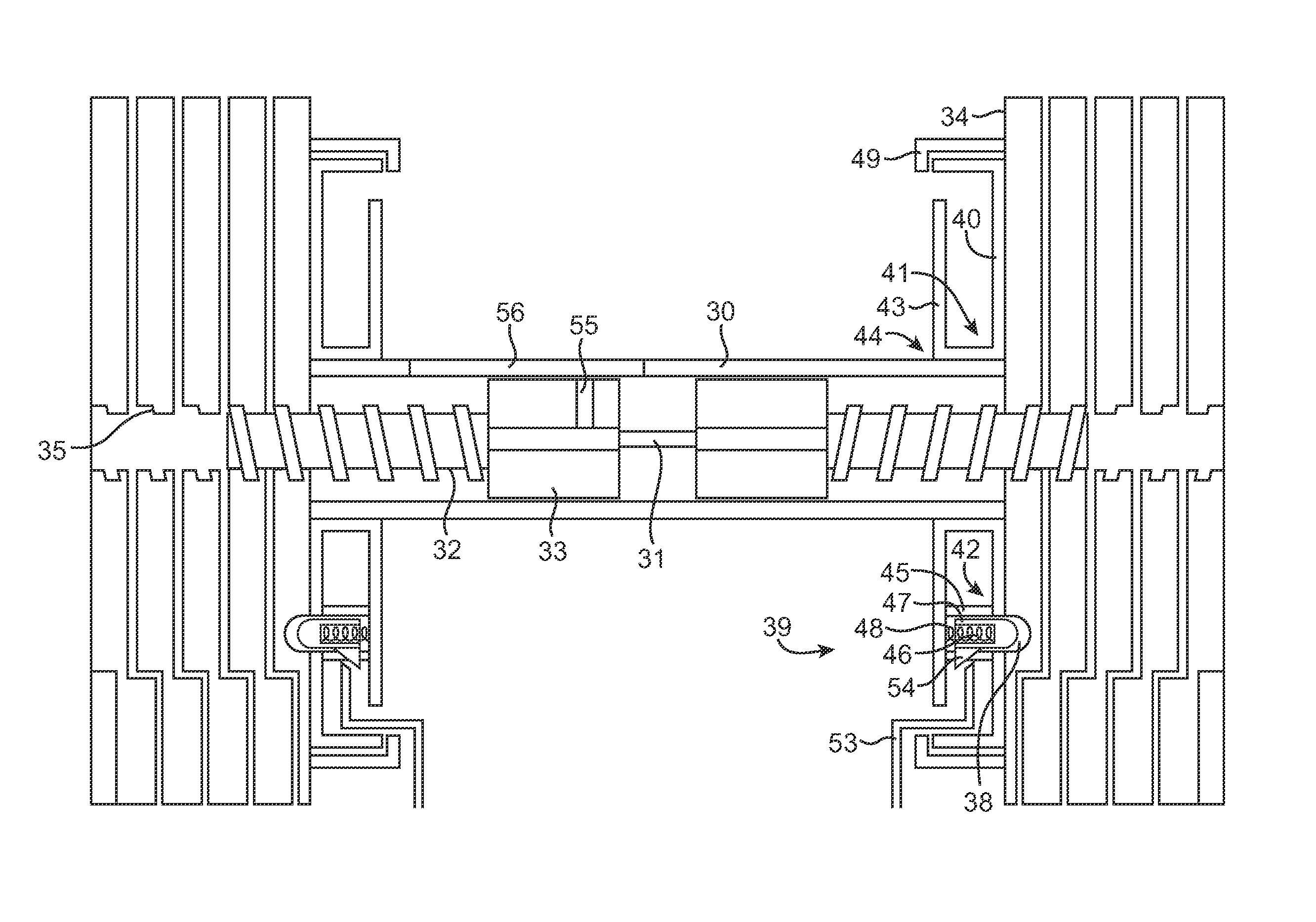
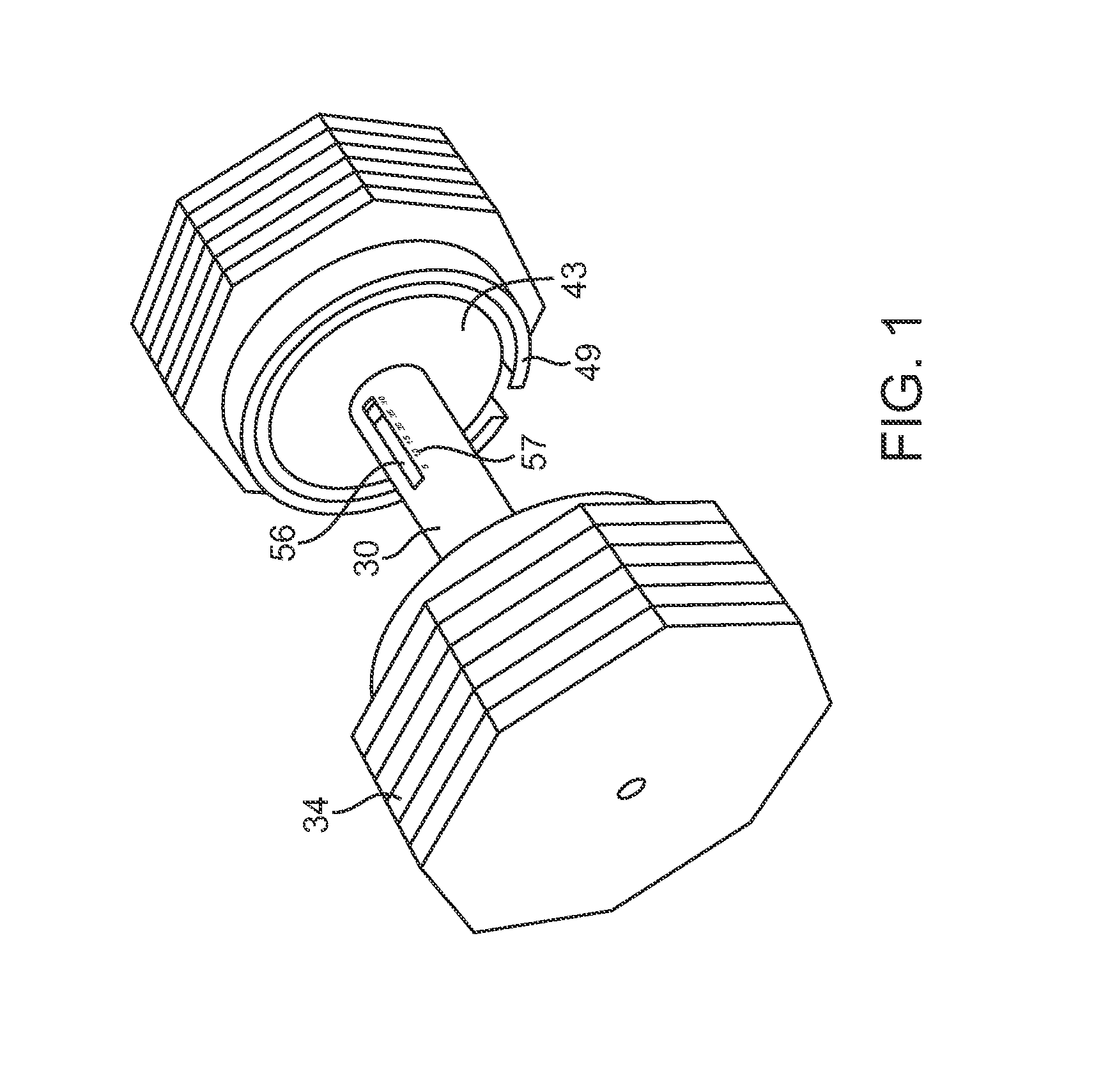
[0025]A tube 30 (FIGS. 1 and 4) has one or more rails 31 attached lengthwise along an inside surface of the tube. Two rotating rods 32 with stop ends 33 are conformed to fit inside an axial passage in the tube 30. The passage preferably has a non-circular cross-section which conforms to the outer periphery of the stop ends 33. An indicator line 55 on the stop end 33 (FIG. 5) of either of the two rotary rods 32 appears through a display window 56 in the tube 30. The indicator line 55 moves axially to selection numbers 57 that appear alongside the display window 56 on the outside surface of the tube 30 as the tube is manually rotated, as described in more detail below. Weights 34 with internally threaded through holes 35 are engaged by the rotary rods 32. At least one weight on each end of the tube 30 is engaged at all times. The outside surface of each weight, with the exception of the outside weights furthest from the tube 30, has a slot 36 (FIG. 6b). The inside surface of each weig...


PUM


Abstract

A dumbbell adjusting system comprises an adjusting system, a stand, and a locking mechanism. The adjusting system includes two rods on the dumbbell's handle which move in and out of the handle to selectively engage the inner threaded through holes of the weights. The weights are configured to interlock with one another so as not to move independently. The locking mechanism unlocks the weights from the handle when the dumbbell is in the stand, allowing the user to select the desired weight, and locks the weights into the handle when the dumbbell is lifted out of the stand.

Description

CROSS-REFERENCES TO RELATED APPLICATIONS[0001]This application claims the benefit of provisional application No. 60 / 635,876, filed on Dec. 13, 2004, the full disclosure of which is incorporated herein by reference.BACKGROUND OF THE INVENTION[0002]1. Field of the Invention[0003]The present invention relates generally to an exercise device and more particularly to an adjustable dumbbell.[0004]U.S. Pat. No. 6,500,101 discloses an adjustable dumbbell comprising two rotating rods that move into and out of through holes of weights by means of a selection knob mounted on a carrying seat. The weights are held by the carrying seat by means of two connection rods held between the weights on opposite ends of the dumbbell.[0005]The connection rods, the four grip rods around the central handle, and the selection device mounted on the carrying seat make the dumbbell bulky and cumbersome to use. They also limit flexibility in the user's wrist which is a problem in exercises that stimulate the fore...

Claims


Application Information

Patent Timeline
IPC IPC(8): A63B21/072A63B21/075
CPCA63B21/0728A63B21/075A63B21/00065
Inventor DOUDIET, ADAM T.
Owner ATD SERVICES
Features
  • Generate Ideas
  • Intellectual Property
  • Life Sciences
  • Materials
  • Tech Scout
  • Unparalleled Data Quality
  • Higher Quality Content
  • 60% Fewer Hallucinations
Learn More