Redundant data and power infrastructure for modular server components in a rack

a rack and server technology, applied in the field of rack mounted computer servers, can solve the problems of multiple rack deployments, the complexity of fully configurable systems, and the fact that it takes hours to wire up and deploy a single rack,

Active Publication Date: 2006-11-21
HEWLETT-PACKARD ENTERPRISE DEV LP
View PDF6 Cites 67 Cited by
  • Summary
  • Abstract
  • Description
  • Claims
  • Application Information

AI Technical Summary

Benefits of technology

[0014]Each modular server chassis preferably includes a plurality of server slots, each server slot configured to accept the server blades. The switches are preferably located on opposite sides of the chassis. In the preferred embodiment, each chassis holds 8 servers and two switches and has a height equivalent to six standard rack units (“Us”) or 10.5″. In contrast with conventional rack mount server systems, the server and network device slots in the preferred embodiment are vertical slots.

Problems solved by technology

Unfortunately, along with this expandability comes the complexity of deploying a fully configurable system.
It can literally take hours to wire up and deploy a single rack.
Deploying multiple racks adds to the complexity because cables are needed for every server in every rack.
This once again adds to the complexity of the system as provisions must be made for space and wiring of the switch / hub.
Unfortunately, modification of a network of rack servers is complicated by the fact that cables often need rerouting and rebundling.
Conventional rack server networks are simply not easily deployed or modified.
Another problem with conventional systems arises when an individual server needs to be replaced.
In this scenario, access to the rear of any individual rack is limited.
As one can see, replacing a single rack mounted server can be inconvenient and time consuming.

Method used


Image

  • Redundant data and power infrastructure for modular server components in a rack
  • Redundant data and power infrastructure for modular server components in a rack
  • Redundant data and power infrastructure for modular server components in a rack

Examples


Embodiment Construction

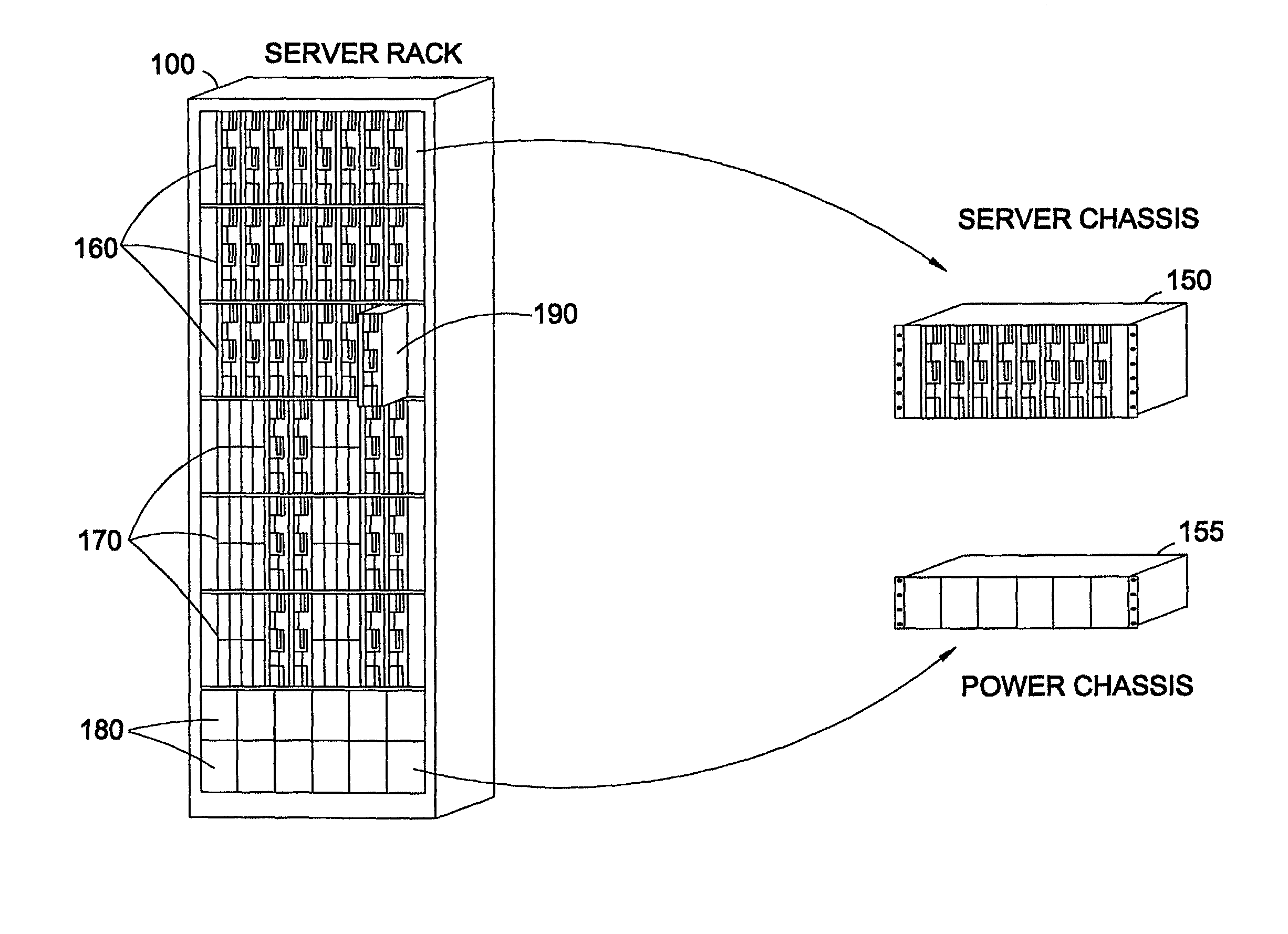
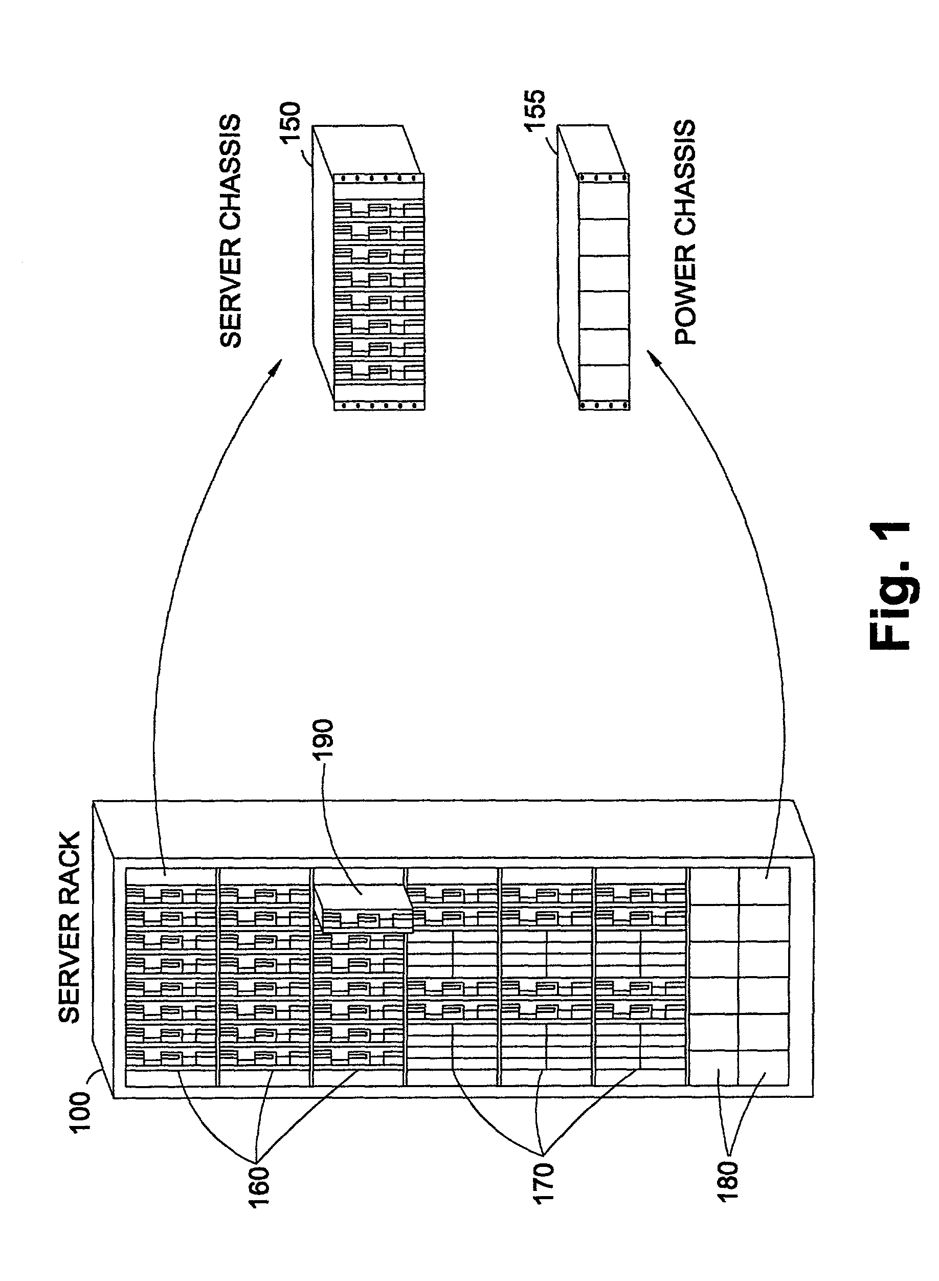
[0028]Referring now to FIG. 1, rack system 100 represents a server rack in accordance with the preferred embodiment. Rack 100 is preferably configured to accept 19 inch wide rack equipment in compliance with EIA width standards and RETMA mounting standards. Rack 100 preferably comprises various chassis, server, and power supply components as depicted. For illustrative purposes, server rack 100 is fitted with hardware comprising different types of servers 160, 170 and power supplies 180. Power supplies 180 are preferably redundant supplies that provide power to servers 160, 170. By way of example, and not by way of limitation, the servers shown in FIG. 1 include application servers 160 and back-end servers 170. Server rack 100 may also be fitted with other hardware and in different configurations as will be recognized by those skilled in the art. For the purposes of this description of the preferred embodiment, however, it may be assumed that the rack includes servers of the type des...


PUM

PropertyMeasurementUnit
widthaaaaaaaaaa
heightaaaaaaaaaa
heightaaaaaaaaaa

Abstract

A modular infrastructure for a computer server rack, comprising modular server chassis, each chassis configured to receive a plurality of servers and two network switches. The switches are redundantly coupled to each server in the same chassis via point to point links within a data backplane. The rack further comprises redundant AC to DC power supplies configured to transmit power to a power backplane in each of the server chassis through a power bus bar. DC power is provided by both power supplies to each server in the rack through the power bus bar and a power backplane located in the same chassis. Each power supply is sufficient to power the entire rack. Servers within separate chassis are coupled into the same network by merely daisy chaining the switches in the rack. Individual servers are deployed by sliding the servers into a server chassis to engage connectors in the backplanes.

Description

CROSS-REFERENCE TO RELATED APPLICATIONS[0001]This application is related to co-pending application Ser. No. 09 / 966,180, filed Sep. 28, 2001 entitled “Intelligent Power Management For A Rack Of Servers.”STATEMENT REGARDING FEDERALLY SPONSORED RESEARCH OR DEVELOPMENT[0002]Not applicable.BACKGROUND OF THE INVENTION[0003]1. Field of the Invention[0004]The present invention generally relates to rack mounted computer servers. More specifically, the preferred embodiment relates to data and power distribution between and among servers within a rack system. More particularly still, the preferred embodiments of the present invention relate to a modular infrastructure for distributing redundant power and data in a rack system.[0005]2. Background of the Invention[0006]Conventional rack mount servers provide a flexible and effective way of providing varying levels of computing power in a relatively small volume. Within a single rack, multiple servers may be coupled together to perform common tas...

Claims


Application Information

Patent Timeline
Patent Type & Authority Patents(United States)
IPC IPC(8): H01B7/30H05K7/14
CPCH05K7/1492
Inventor SANDERS, DECEASED, MICHAEL C.MCDANIEL-SANDERS, LEGAL REPRESENTATIVE, VIVIANNGUYEN, JOHN D.PASCARELLA, RANDALL
Owner HEWLETT-PACKARD ENTERPRISE DEV LP
Why Eureka
Try Eureka