Video noise floor estimator with impulse noise detection

a technology of impulse noise detection and video noise, applied in the field of image processing, can solve problems such as noise in video equipment, noise in analog and digital domain conversion, and adversely affect the signal to noise ratio (snr)

Active Publication Date: 2006-11-21
TEXAS INSTR INC
View PDF27 Cites 19 Cited by
  • Summary
  • Abstract
  • Description
  • Claims
  • Application Information

AI Technical Summary

Problems solved by technology

Noise in video equipment may arise from electrical distortions and interference created by power supply hum interactions between internal electrical components, etc.
For example, conversion between analog and digital domains leads to noise.
Any of these factors or a combination of them, can combine to adversely affect the signal

Method used


Image

  • Video noise floor estimator with impulse noise detection
  • Video noise floor estimator with impulse noise detection

Examples


Embodiment Construction

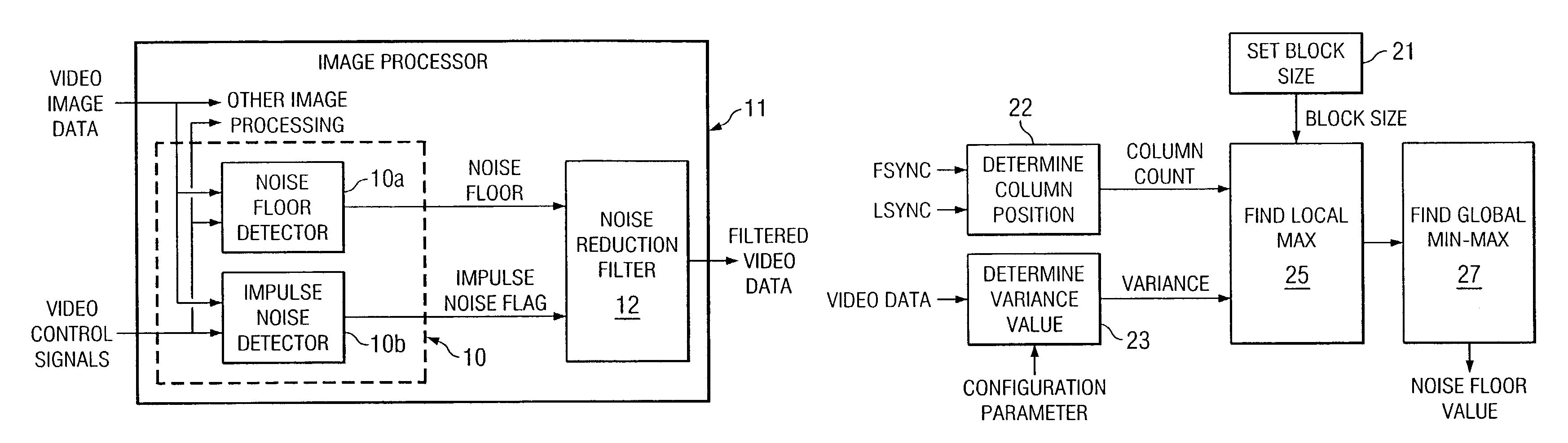
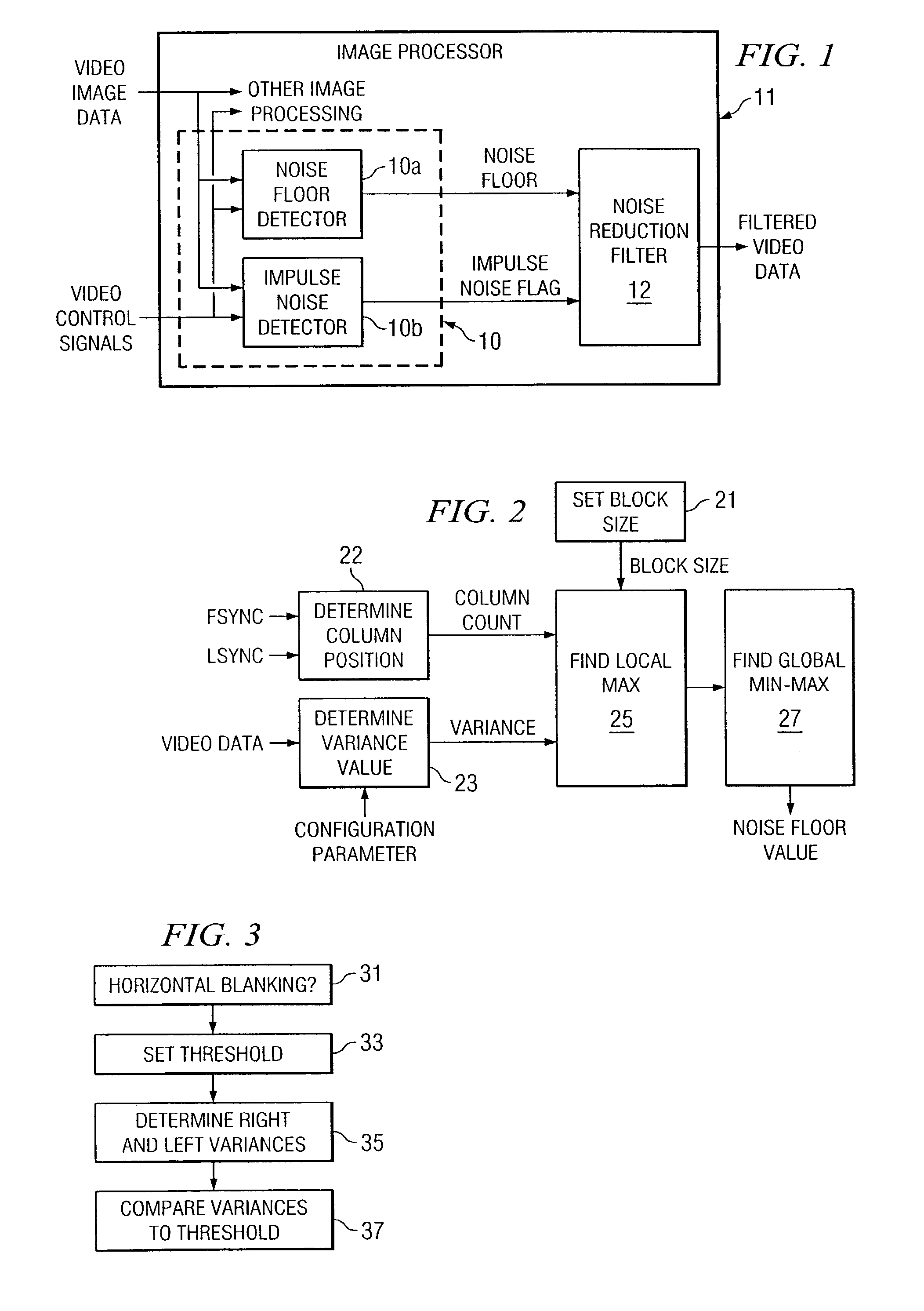
[0009]The following description is directed to a method for determining the type of noise reduction filter (linear or non linear) appropriate for a particular incoming stream of video data. This is accomplished by detecting both linear noise and impulse (non linear) noise. If the noise is linear, a noise floor is calculated so that it can also be determined how much smoothing to perform.

[0010]FIG. 1 illustrates a noise detection unit 10 in accordance with the invention. As indicated, noise detection unit 10 is implemented with programming and a processor, which may be incorporated into a larger image processing system 11. Apart from the features of the present invention, image processing system 11 may be implemented with known techniques and processing and memory devices. Image processing system 11 includes a noise reduction filter 12, which implements algorithms for smoothing and impulse noise reduction.

[0011]Noise detection unit 10 receives input video data, which includes the ima...


PUM


Abstract

A method of detecting both linear and non linear noise in video data. Linear noise is detected on a line-by-line basis, by blocks within each line. Non linear noise is detected during horizontal blanking periods. The method provides a noise floor value for linear noise and an impulse noise flag for non linear noise, both of which are delivered to a noise reduction filter.

Description

TECHNICAL FIELD OF THE INVENTION[0001]This invention relates to image processing, and more particularly to a method of calculating a noise floor in video images, as well as impulse noise.BACKGROUND OF THE INVENTION[0002]Noise in video equipment may arise from electrical distortions and interference created by power supply hum interactions between internal electrical components, etc. Noise may also be in the form of distractions from the pure signal transference, modification or amplification. For example, conversion between analog and digital domains leads to noise. Any of these factors or a combination of them, can combine to adversely affect the signal to noise ratio (SNR).[0003]Although some noise is found in all video systems, the lower the noise rating of a component the better. Noise can be a problem if one wants to attain enhanced detail. At some point, the signal actually is lower in power than the noise itself (the noise floor), resulting in the true signal being obscured. ...

Claims


Application Information

Patent Timeline
IPC IPC(8): H04N5/21G06K9/38G06K9/40H04N5/213H04N5/217
CPCH04N5/21H04N5/213
Inventor KEMPF, JEFFREY
Owner TEXAS INSTR INC
Why Eureka
Try Eureka