Distortion reduction in a wireless communication device

a wireless communication and reduction technology, applied in the direction of electrical equipment, radio transmission, transmission, etc., can solve the problems of interference with the desired signal, increased interference between wireless communication systems, and possible interferen

Inactive Publication Date: 2006-11-21
QUALCOMM INC
View PDF10 Cites 50 Cited by
  • Summary
  • Abstract
  • Description
  • Claims
  • Application Information

AI Technical Summary

Benefits of technology

[0019]In the feedforward system a conventional radio receiver receives the radio frequency signal at a selected radio frequency. The received RF signal contains both the desired signal and the jammer signal. A conventional mixer core converts the received RF signal to a selected processing frequency. In this implementation, the invention comprises a down-mixer to convert the received RF signal to a selected lower frequency with the filter operating at the selected lower frequency to remove the desired signal. The system further comprises an up-mixer coupled to the filter to convert the filtered signal to the selected radio frequency. The adder operates at the selected radio frequency to remove the jammer signal and generate an output signal that is coupled to the mixer core. In this manner, the undesirable jammer signal is eliminated prior to processing by the mixer core.

Problems solved by technology

Due to this crowding, increased interference between wireless communication systems is commonplace.
In this situation, interference may be likely.
One example of such interference occurs in a code division multiple access (CDMA) wireless system.
However, the difference signal, designated herein as ΔωJ, may well be inside the desired channel and thus cause significant interference with the desired signal.
In this circumstance, the AMPS signals are considered a jammer signals since they create interference and therefore jam the desirable CDMA signal.
If this second-order distortion signal is inside the channel bandwidth, the jammer rejection filters 28 and 30 will be ineffective and the resultant interference may cause an unacceptable loss of carrier-to-noise ratio.
Only the frequency separation is important if the second-order distortion results in the introduction of an undesirable signal into the channel bandwidth of the CDMA unit.
It should be noted that the second-order distortion discussed herein is a more serious problem using the direct down-conversion architecture illustrated in FIG. 1.
Therefore, the IIP2 specification for a super-heterodyne receiver is generally not difficult to achieve.
The IIP2 requirement is often the single most difficult parameter to achieve in a direct down-conversion receiver architecture.
While various calibration schemes may be effective to reestablish symmetry in the mixer 20, this calibration is time-consuming and will vary from one wireless unit to the next due to component variations.
Such time-consuming calibration processes are expensive do not lend themselves well to high-volume production since the calibration must be done initially at the factory and may require periodic recalibration during normal use.
In addition to the calibration difficulties, the undesirable second-order products are generally quite low relative to the desired signal and are thus not directly measurable.
All these factors lead to difficulty in reducing the second-order distortion products to an acceptable level.

Method used


Image

  • Distortion reduction in a wireless communication device
  • Distortion reduction in a wireless communication device
  • Distortion reduction in a wireless communication device

Examples


Embodiment Construction

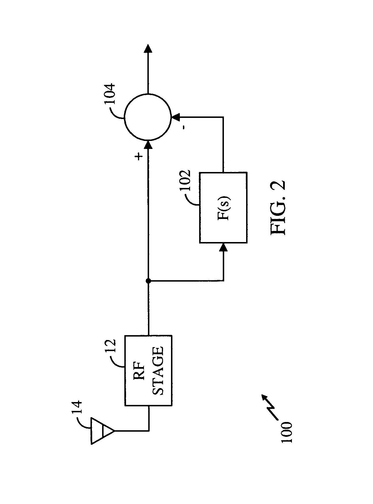
[0029]The present invention is directed to a system architecture that actively cancels out the undesirable portions of the signals, which may be referred to herein as jammer signals. Although different implementations may be used, the underlying principle is best illustrated in the functional block diagram of FIG. 2 where a system 100 implements the present invention. The RF stage 12 and antenna 14 are conventional components that need not be described in greater detail herein. A filter 102 having a filter function F(s) serves to remove the desirable portion of the received signal. Details of the filter 102 will be provided below.

[0030]The output of the filter 102 is the undesirable jammer signal. The output of the filter 102 (i.e., the jammer signal) is combined with the output of the RF stage 12 by an adder 104. A positive input of the adder 104 is coupled to the output of the RF stage 12 while a negative input of the adder is coupled to the output of the filter 102. The adder 104...


PUM


Abstract

The present invention provides a technique for cancellation of jammer signals in a radio frequency receiver. A radio frequency signal contains both a desirable signal and an undesirable jammer signal. The combined signal is processed with a filter (104) to extract only the undesirable jammer signal. The jammer signal is then added (104) back to the combined signal to effectively cancel the jammer signal. The system may be implemented using a feedforward approach or a feedback approach. The resultant clean signal is processed in a conventional manner.

Description

BACKGROUND[0001]1. Field of the Invention[0002]The present invention is related generally to wireless communication devices, and, more particularly, to a system and method for distortion reduction in a wireless communication device.[0003]2. Description of the Related Art[0004]The present invention provides this, and other advantages, as will be apparent from the following detailed description and the accompanying figures.[0005]Wireless communication systems are proliferating as more and more service providers add additional features and technical capabilities. A large number of service providers now occupy a relatively limited portion of the radio frequency spectrum. Due to this crowding, increased interference between wireless communication systems is commonplace. For example, wireless communication systems from two different service providers may occupy adjacent portions of the spectrum. In this situation, interference may be likely.[0006]One example of such interference occurs in...

Claims


Application Information

Patent Timeline
Patent Type & Authority Patents(United States)
IPC IPC(8): H04B1/10H04B1/12H04B1/707
CPCH04B1/123H04B1/7101
Inventor SHAH, PETER JIVAN
Owner QUALCOMM INC
Why Eureka
Try Eureka