Lightweight mobile lift-assisted patient transport device

a mobile, patient technology, applied in the direction of transportation and packaging, tables, applications, etc., can solve the problems of patient drop or rough handling of patients, constant risk to the ems crew and to the patient,

Inactive Publication Date: 2006-11-28
BISHOP JOSEPH +3
View PDF28 Cites 44 Cited by
  • Summary
  • Abstract
  • Description
  • Claims
  • Application Information

AI Technical Summary

Benefits of technology

[0013]One embodiment of a lift-assisted device comprises a patient support structure having a movable yoke, a base, and an undercarriage extending between the patient support structure and the base. At least one pneumatic cylinder extends between the movable yoke and a part of the patient support structure for applying a driving force on the movable yoke to raise or lower the patient support structure with respect to the base.
[0014]Another aspect of the invention involves a lift-assisted device comprising a patient support structure having a movable part, a base, an undercarriage extending between the patient support structure and the base, a power source for applying a driving fo...

Problems solved by technology

Such transport involves a constant risk to the EMS crew and to the patient.
The risk arises from the activity involving the EMS crew, usually two persons, lifting and moving the patients.
There is also the danger that the patient may be dropped or roughly handled while being moved.
As for the EMS crew, they are routinely faced with lifting situations which can and often do result in significant and even crippling back injuries.
The dangers of lifting-related injury is compounded because an EMS crew must lift a patient approximately 7 times during the course of a call.
A particularly difficult part of this process results from the fact that the typical device that is used in the field, e.g., a stretcher for transfer of patients via ambulances, is not well-designed for lifting and lowering.
Because of the location of the undercarriage and supporting structure, the members of the EMS crew cannot simply stand on each side of the device and lift or lower it using proper lifting techniques with their legs.
This consequence results in a significant number of disabling back injuries to EMS personnel each year.
In addition, because of the strength that is required to lift and lower a device...

Method used


Image

  • Lightweight mobile lift-assisted patient transport device
  • Lightweight mobile lift-assisted patient transport device
  • Lightweight mobile lift-assisted patient transport device

Examples


Embodiment Construction

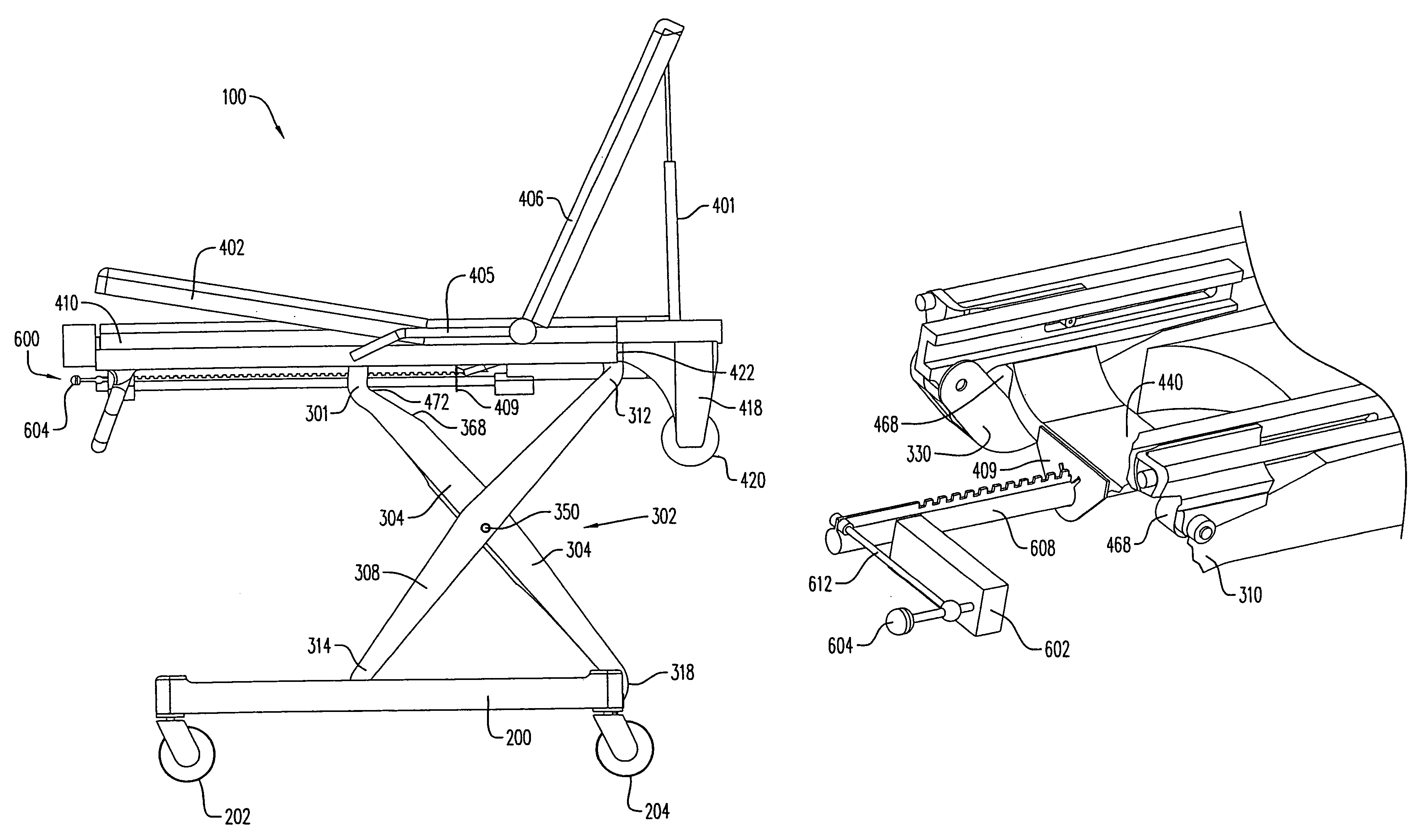
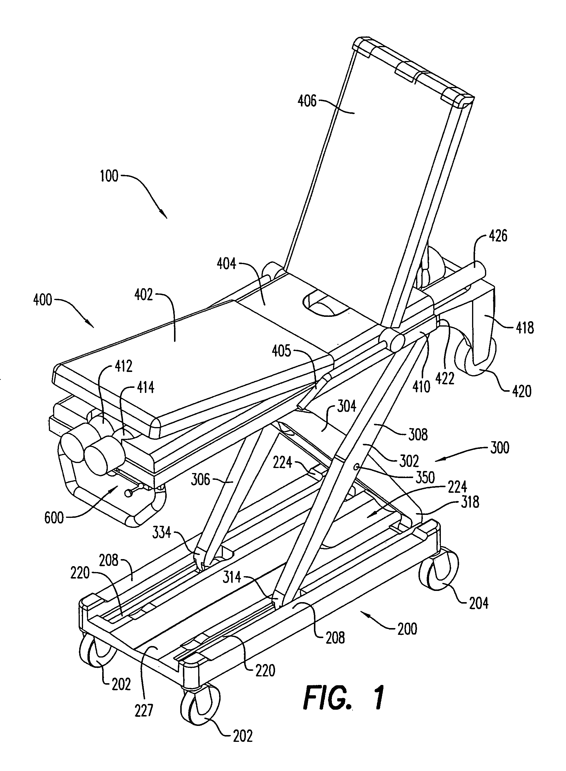
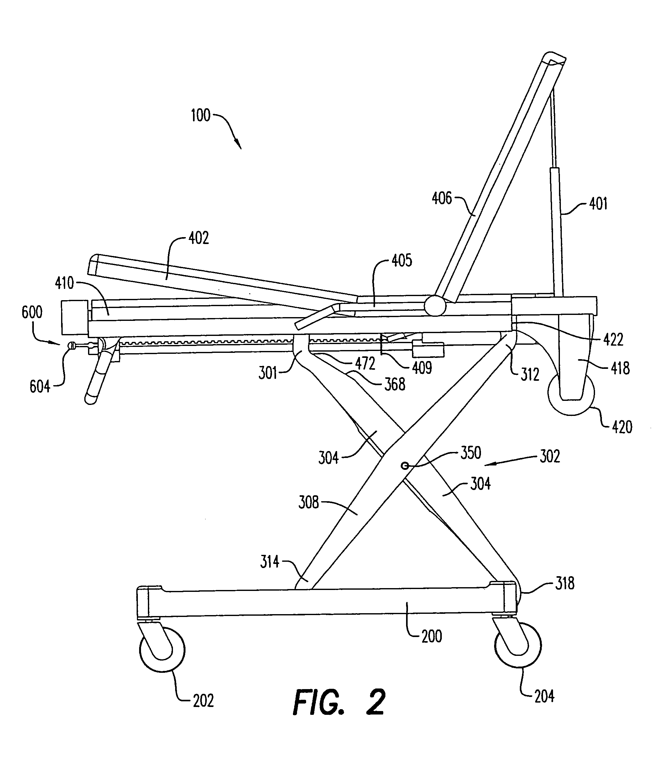
[0034]FIG. 1 illustrates a perspective view of an exemplary embodiment of a mobile lift-assisted device 100. The mobile lift-assisted device 100 is generally used to transport patients from one location to another, while allowing a patient to be placed in a desired position. Furthermore, the mobile lift-assisted device 100 is able to elevate and lower an object or person to a desired height.

[0035]As shown in the exemplary embodiment in FIG. 1, the lift-assisted device 100 generally includes three main structural portions which include: the base 200, the undercarriage 300, and the patient support structure 400. A height adjustment and locking system 600 controls the height of the patient support structure 400.

[0036]Advantageously, most of the components of the base 200, undercarriage 300, and patient support structure 400 are constructed using monocoque or similar construction techniques utilizing carbon-fiber composites or like material.

[0037]The base 200 is the terrain-engaging sec...


PUM


Abstract

A lift-assisted device having a patient support structure, a base, and an undercarriage. The device can be powered by a pneumatic cylinder and a compressed gas source. The undercarriage can be a scissors linkage having at least one first member being slidably connected to the patient support structure an upper end of the first member and pivotally connected to the base at a lower end of the first member, and at least one second scissors linkage member, the second scissors linkage member being pivotally connected to the first scissors linkage member. An upper end of the second member is pivotally connected to the patient support structure, and a lower end of the second member is pivotally connected to the base. The pneumatic cylinder is arranged for moving the upper end of the first member and the lower end of the second member with respect to the patient support structure.

Description

[0001]This application is a continuation-in-part of application Ser. No. 10 / 621,304, filed in the United States on Jul. 18, 2003 now abandoned, the entire contents of which are hereby incorporated by reference.FIELD OF THE INVENTION[0002]The present invention relates generally to mobile lift-assisted transport devices for transporting patients. More specifically, the present invention relates to a mobile lift-assisted transport device which is able to easily be elevated and lowered.BACKGROUND[0003]A busy Emergency Medical Services (EMS) crew may handle as many as 20 calls during the work shift. Typically one or more such calls involve moving a patient from a field location, such as his home or the scene of an accident, to a health care facility such as an emergency room at a hospital.[0004]Providing transport for the patient involves various procedures for appropriately securing the patient in different transport vehicles for transport to the hospital or other appropriate destinatio...

Claims


Application Information

Patent Timeline
IPC IPC(8): A61G1/02A61G7/10B62B19/00A61GA61G1/00A61G1/04A61G1/06A61G7/012A61G7/015
CPCA61G1/0293A61G1/04A61G1/0567A61G1/0237A61G1/0262A61G1/0212A61G1/0268A61G1/0218A61G7/012A61G7/015A61G2001/042A61G1/042
Inventor BISHOP, JOSEPHCATOE, MICHAEL W.ALGIE, DAVID G.ALGIE, IAN G.
Owner BISHOP JOSEPH
Why Eureka
Try Eureka