Round baler bale ejecting arrangement

Active Publication Date: 2006-11-28
DEERE & CO
View PDF4 Cites 18 Cited by
  • Summary
  • Abstract
  • Description
  • Claims
  • Application Information

AI Technical Summary

Benefits of technology

[0008]The object is accomplished in a bale-forming belt tensioning arm arrangement including at least one tensioning arm assembly mounted for pivoting downwardly into, and upwardly from, an upper front region of a baling chamber provided for containing a bale being formed, the arm assembly having a lower end which engages the bale-forming belts in a region between two fixed bale-forming belt support rolls so as to create a loop of belt material, when no bale is present in the

Problems solved by technology

A drawback associated with the tensioning arm arrangement disclosed in U.S. Pat. No. 6,640,699 and with the tensioning arm arrangements disclosed in the above-identified patent applications is that bale ejection is not positive enough to consistently effect the discharge of a wedged bale.
A further drawback associated with the tensioning arm arrangements disclosed in the above-identified patent applications is that the tensio

Method used


Image

  • Round baler bale ejecting arrangement
  • Round baler bale ejecting arrangement
  • Round baler bale ejecting arrangement

Examples


Embodiment Construction

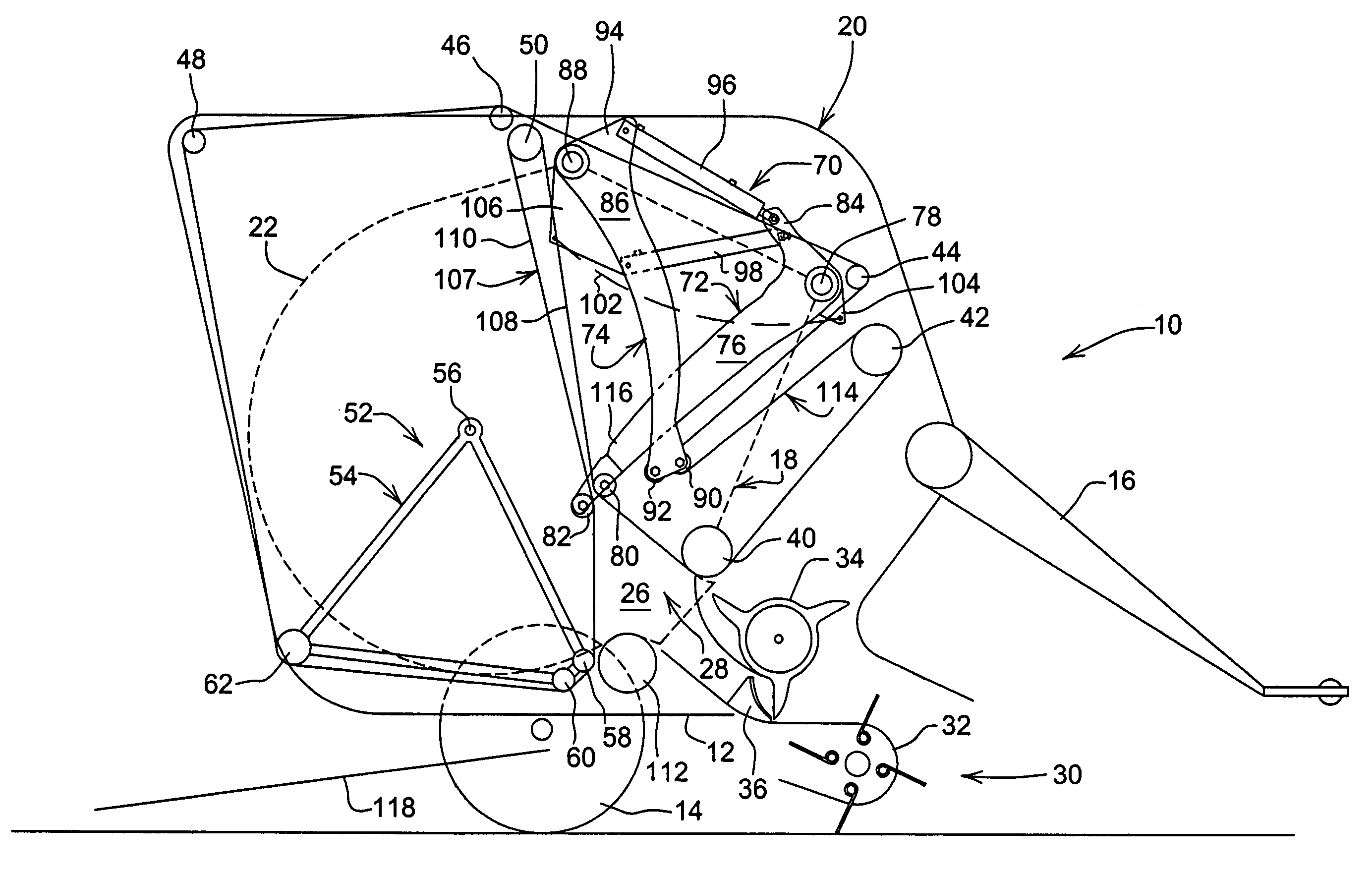
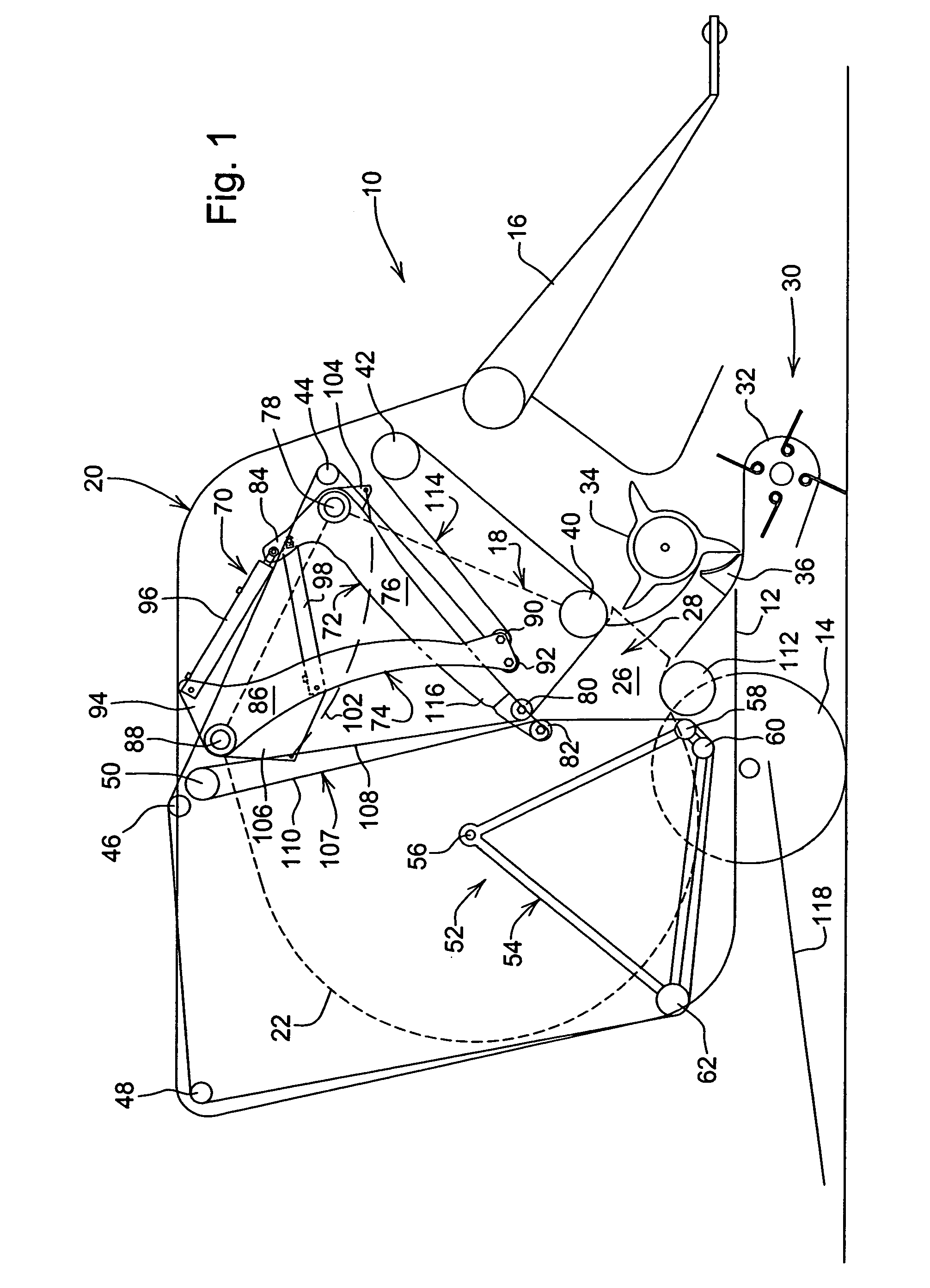
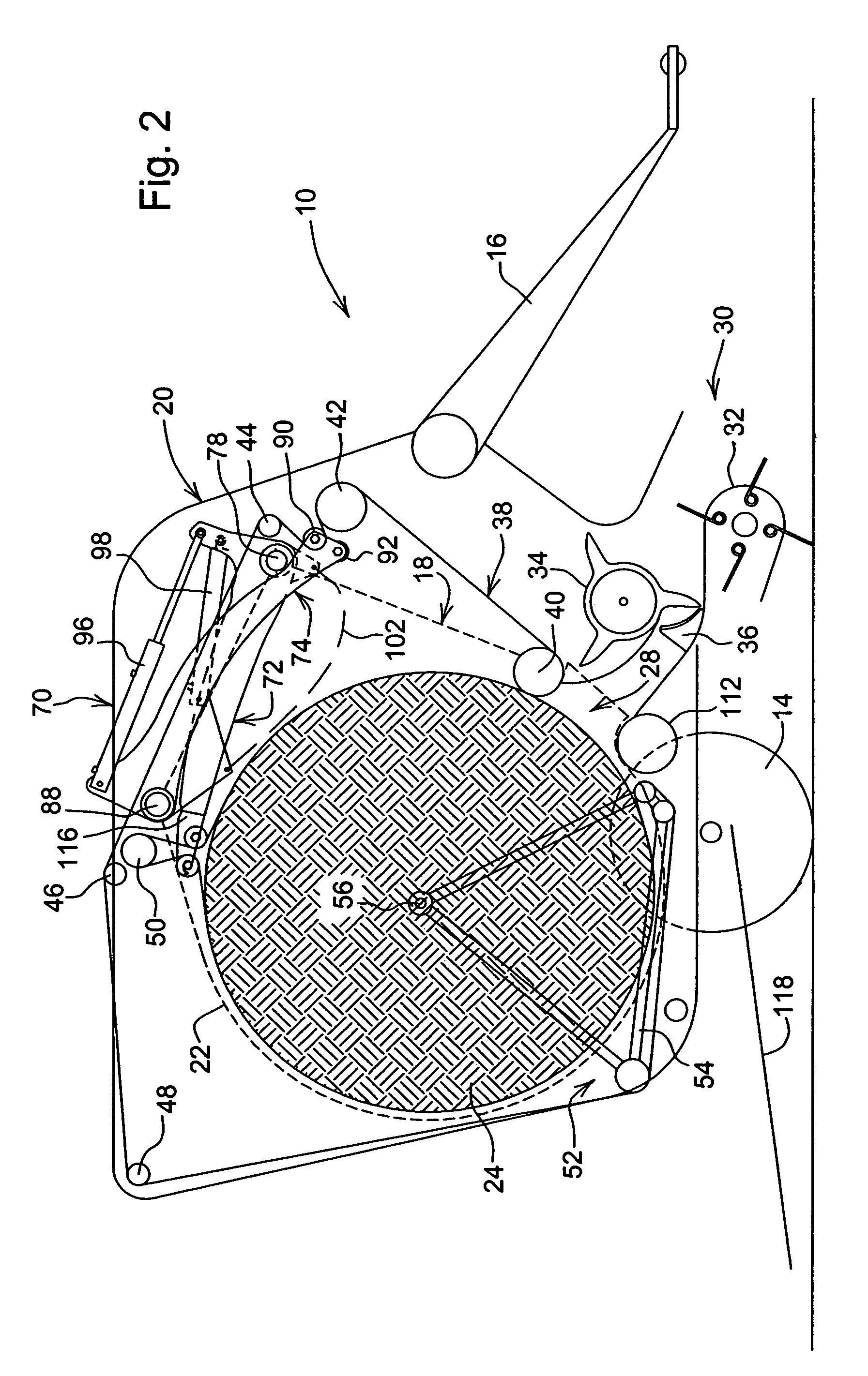
[0016]Referring now to FIGS. 1–3 of the drawings, there is shown a large round baler 10 including a chassis 12 carrying an axle on which ground wheels 14 are mounted so that the chassis 12 is supported for being towed over the ground by an agricultural tractor, not shown, coupled to a tongue 16 joined to, and projecting forwardly from the chassis 12. The chassis 12 includes a pair of transversely spaced sidewall structures including an inner pair of vertically oriented side walls 18, which are parallel to, and respectively spaced transversely from, a pair of outer sidewalls 20, with the inner walls 18, being shown only in dashed outline, for the sake of clarity. The inner sidewalls 18 have a rear region shaped so as to define a partial circular outer periphery 22 having a radius slightly larger than that of a full sized bale 24 (FIGS. 2 and 3) formed within an expansible baling chamber 26, described in more detail below, as crop is fed through an inlet 28 of the baling chamber by th...


PUM


Abstract

A large round baler includes a combined tensioning and ejecting arrangement comprising a tensioning arm assembly mounted to an upper front region of the baler sidewalls. The tensioning arm assembly operates such that, after formation of a bale in the baling chamber and the discharge gate has been swung to its raised discharge position, the tensioning arm assembly pivots into a region occupied by the completed bale so as to positively eject the bale. The combined tensioning and ejecting arrangement includes front and rear arm assemblies which define a compact assembly and share a pair of double-acting tensioning actuators and a single-acting ejection actuator. The tensioning arm assembly may be used with a baler having a light weight bale discharge gate or with a baler having a discharge gate formed in part by rear sections of sidewalls forming opposite sides of the baling chamber. In an alternate embodiment, the ejection actuator is replaced with a coil extension spring.

Description

FIELD OF THE INVENTION[0001]The present invention relates to round balers, and more particularly, relates to ejecting a bale from a variable sized baling chamber.BACKGROUND OF THE INVENTION[0002]The bale-forming belts in known variable chamber balers are supported by a combination of fixed and movable belt support rolls, with some of the movable belt support rolls being carried by tensioning arms mounted for vertical pivotal movement, so as to control loops of excess lengths of bale-forming belts, at a start of a bale, with the tensioning arms being biased so as to yieldably resist movement in a direction permitting lengths of belting to be pulled out from the loops as the bale expands in size. The density of the formed bale depends upon the resistance to the belt expansion during formation of the bale. Once formation of the bale is completed, a discharge of the bale from the baling chamber is accomplished by opening a bale discharge gate which elevates a section of the bale-forming...

Claims


Application Information

Patent Timeline
IPC IPC(8): B30B5/04
CPCA01F15/0883
Inventor ANSTEY, HENRY DENNISDERSCHEID, DANIEL ERIC
Owner DEERE & CO
Why Eureka
Try Eureka