Vacuum pump for agricultural seeding equipment

a vacuum pump and agricultural technology, applied in the field of vacuum pumps, can solve the problems of large pumps, costly hydraulic motors, and high rpm requirements, and achieve the effect of simplifying maintenance or replacemen

Active Publication Date: 2006-11-28
DEERE & CO
View PDF6 Cites 8 Cited by
  • Summary
  • Abstract
  • Description
  • Claims
  • Application Information

AI Technical Summary

Benefits of technology

[0010]The design of the impeller allows air to be discharged from the impeller in a 360 degree pattern and avoids channeling the air into a single air stream. This allows the impeller size to be increased without significantly increasing the overall size of the pump.
[0012]The impeller includes a center hub surrounding the central aperture, located in registry with the impeller inlet, and located between base ends of the impeller vanes. The center hub has a curved, substantially conical taper or shape that acts to smoothly direct the incoming air approximately 90° to enter the air passages between vanes. The center hub and center cap design of the impeller are configured to reduce or to eliminate a stagnant air spot in the center of the impeller by imparting a movement to the incoming air, causing a smooth flow transition to the base ends of the vanes.
[0016]As another aspect of the invention, the removal of the impeller from the motor output shaft for maintenance or replacement is simplified. The cap is unscrewed and removed, and the nut is unscrewed and removed. The impeller at this point is effectively press fit onto the drive output shaft and manual removal is difficult. According to this aspect the invention, the cap can be screwed back into the opening, until the end of the shank portion abuts the end of the shaft. Further tightening of the cap drives the impeller off the shaft in the axial direction. In other words, the force generated by the center cap being reinstalled into the threaded region of the central aperture slides the impeller assembly off the taper on the shaft.

Problems solved by technology

These pumps can be large and cumbersome.
This rpm requirement can necessitate a costly hydraulic motor for the vacuum pump.

Method used


Image

  • Vacuum pump for agricultural seeding equipment
  • Vacuum pump for agricultural seeding equipment
  • Vacuum pump for agricultural seeding equipment

Examples


Embodiment Construction

[0029]While this invention is susceptible of embodiment in many different forms, there are shown in the drawings, and will be described herein in detail, specific embodiments thereof with the understanding that the present disclosure is to be considered as an exemplification of the principles of the invention and is not intended to limit the invention to the specific embodiments illustrated.

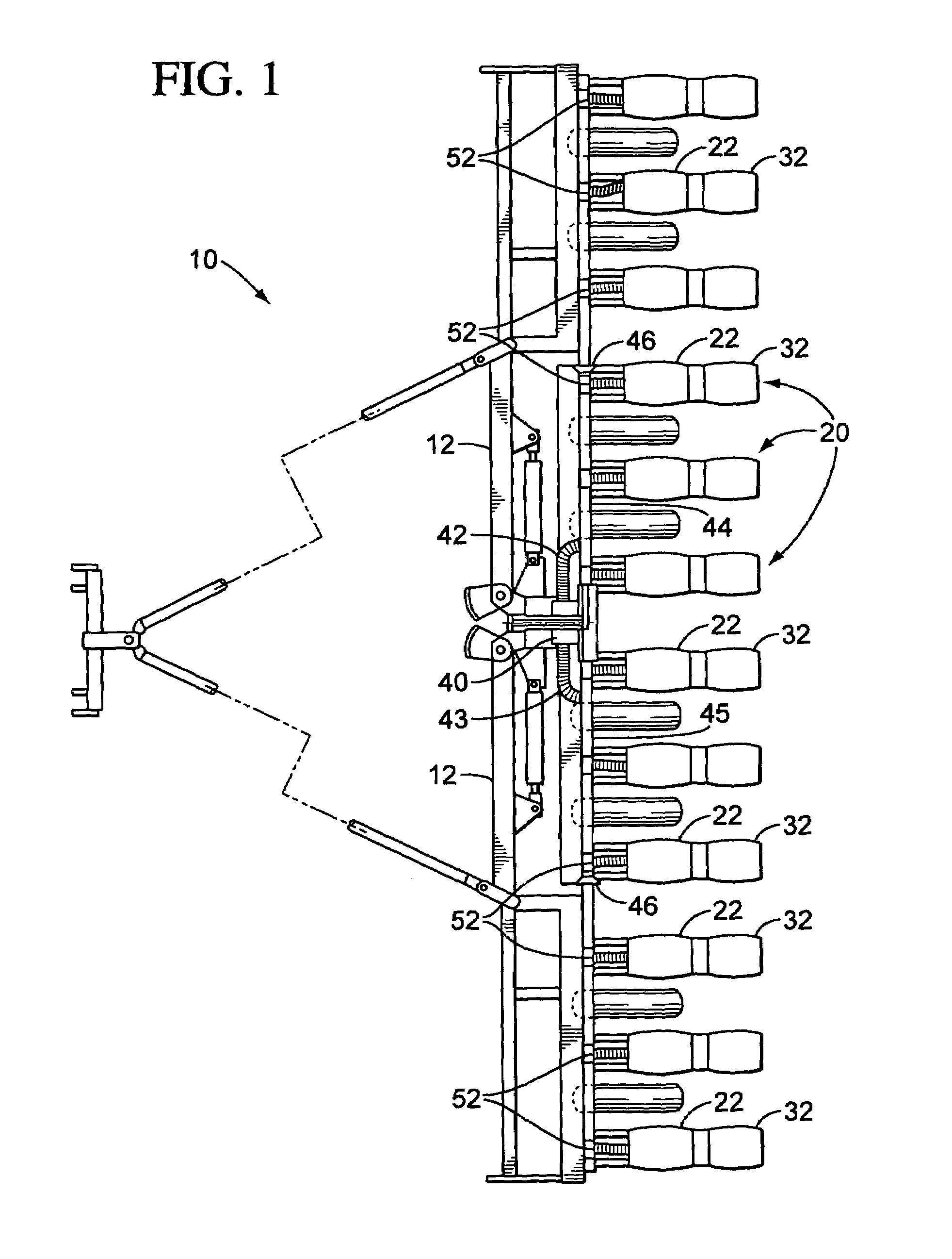
[0030]FIG. 1 is a top view of a seeding machine 10. In the illustrated embodiment, the seeding machine is a row crop planter; however, the present invention could be used on other seeding machines having pneumatic seed meters, including grain drills and air seeders. The planter can be configured as described in U.S. Pat. No. 6,308,646 or 6,644,225, herein incorporated by reference. The planter comprises a frame 12 that can be extended into a working configuration illustrated in FIG. 1 and folded into a transport configuration. A plurality of row crop planting units 20 is mounted to the frame 12.

[...


PUM


Abstract

A vacuum pump for a seed planter includes a housing, an impeller rotated within the housing, and a motor or other drive. The housing has a central inlet and a circumferentially arranged outlet passage. The impeller vanes define air paths that are open to the outlet passage. The impeller has a central aperture for coupling to the output shaft of the drive and an impeller center cap screwed into the central aperture. The impeller has a curved conical center hub that surrounds the central aperture. The center hub and the center cap are configured to smoothly direct air flow to the passages between the vanes to reduce or eliminate a stagnant air region in a center of the impeller. The center cap can also be used as a tool to remove the impeller from the output shaft.

Description

TECHNICAL FIELD OF THE INVENTION[0001]The invention relates to vacuum pumps, and particularly vacuum pumps used in agricultural seed planters utilizing vacuum controlled seed meters.BACKGROUND OF THE INVENTION[0002]In a typical agricultural seed planter, a plurality of seed meters are arranged in a row corresponding to furrows to be seeded. Such a seed planter is disclosed in U.S. Pat. No. 6,308,646 or U.S. Pat. No. 6,644,225. Each seed meter is supplied with a supply of seeds. A seed meter disk is rotated within the seed meter in communication with the supply of seeds while a vacuum is applied to an opposite side of the disk. The seed meter discharges seed at a predetermined rate along the furrow. Such a seed meter is disclosed for example in U.S. Pat. No. 5,170,909.[0003]To supply the vacuum to each seed meter, a vacuum pump is arranged on the seed planter. Typically, the vacuum pump used on agricultural seed planters is an off-the-shelf centrifugal fan or blower implemented in su...

Claims


Application Information

Patent Timeline
Patent Type & Authority Patents(United States)
IPC IPC(8): G01F11/20A01C7/04
CPCA01C7/042
Inventor BRUEGGEN, SHANE
Owner DEERE & CO
Why Eureka
Try Eureka