Airbag device

Inactive Publication Date: 2006-11-28
TOYODA GOSEI CO LTD
View PDF8 Cites 10 Cited by
  • Summary
  • Abstract
  • Description
  • Claims
  • Application Information

AI Technical Summary

Benefits of technology

[0013]Therefore, the airbag device according to the present invention facilitates a connecting work of the airbag and the inflator by dispensing a diffuser but using only a clamp. Moreover, even if the inflator is actuated before the airbag is connected to the inflator, thrust force is not applied to the inflator.
[0015]With this construction, the raised portion prevents the clamp from slipping off the inflator, which improves a connecting strength of the airbag and the inflator.
[0017]With this construction, the clamp hardly moves in front or rear direction in the axial direction of the inflator, which further improves the connecting strength of the airbag and the inflator.

Problems solved by technology

However, with this construction, the inflator has to be inserted into a tubular inlet port of the airbag to be connected with the airbag so that the gas discharge ports on the outer circumference of the end portion may not be closed.

Method used


Image

  • Airbag device
  • Airbag device
  • Airbag device

Examples


Embodiment Construction

[0029]Preferred embodiments of the present invention are described below with reference to the accompanying drawings. However, the invention is not limited to the embodiments disclosed herein. All modifications within the appended claims and equivalents relative thereto are intended to be encompassed in the scope of the claims.

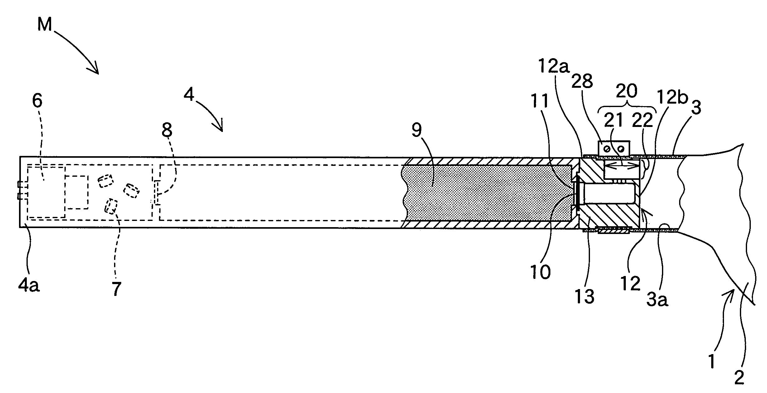
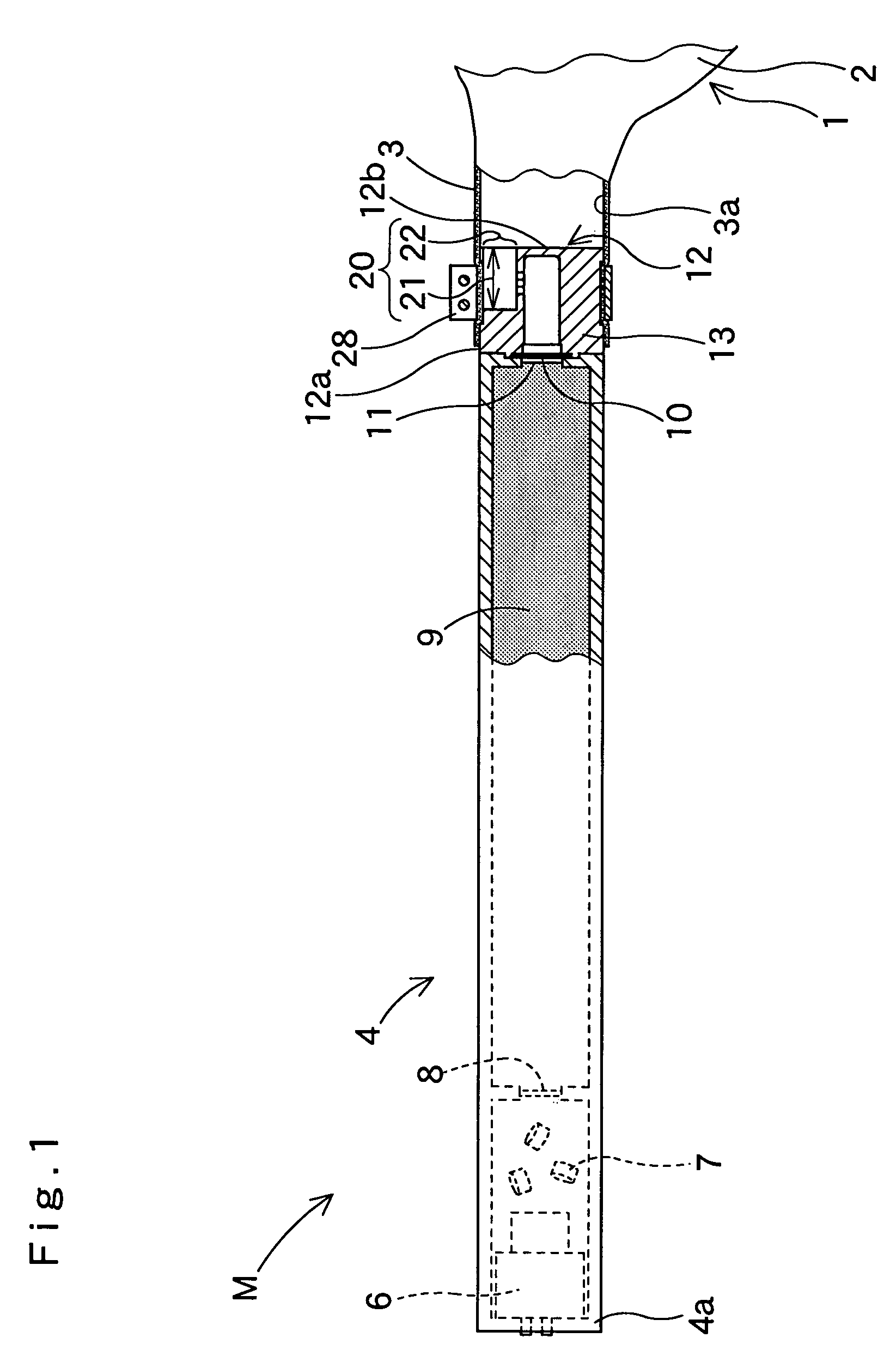
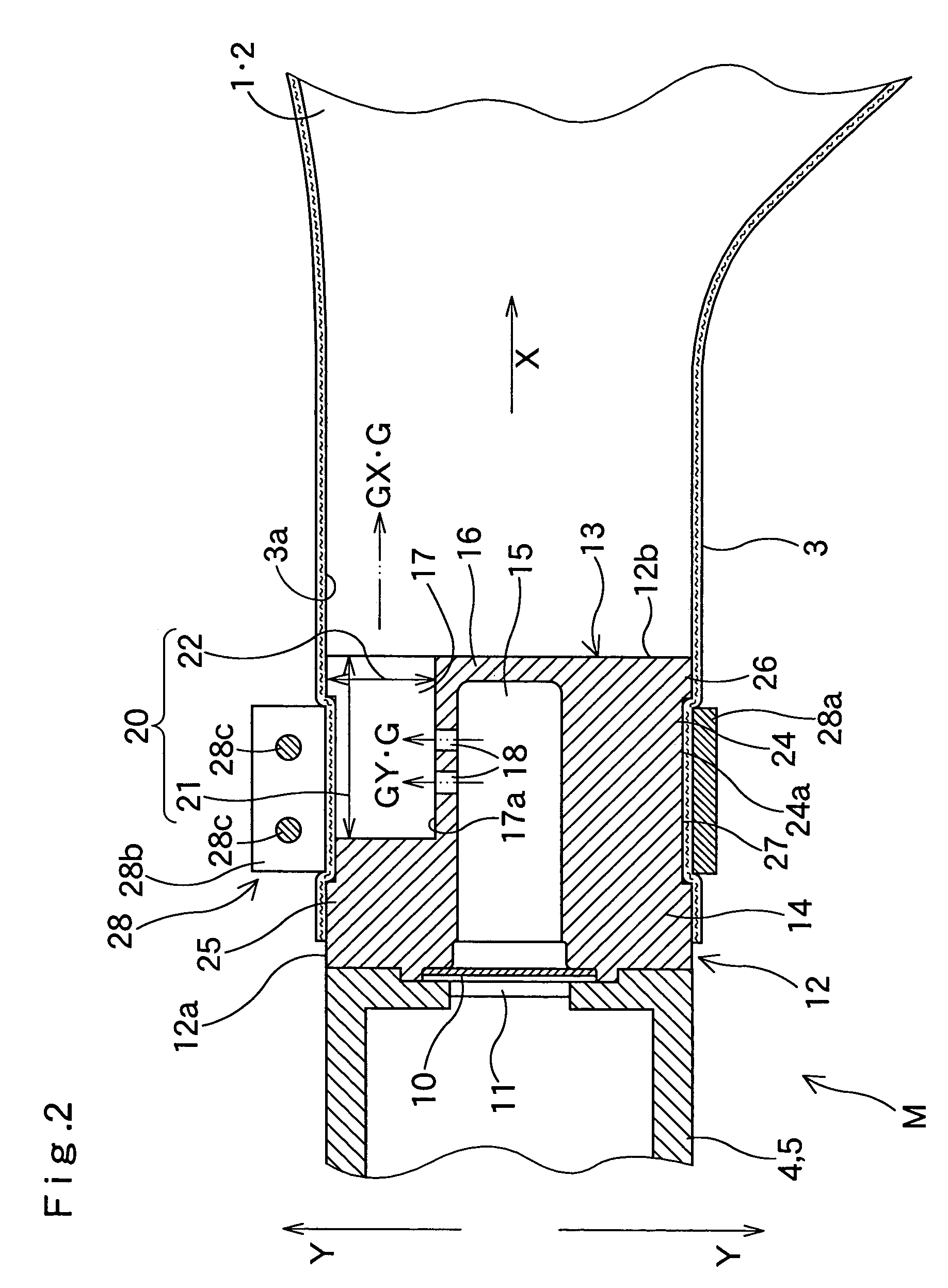
[0030]FIGS. 1 to 4 illustrate an embodiment of the airbag device M of the present invention. The airbag device M is a head-protecting airbag device located above side windows of a vehicle, and includes an airbag 1 and an inflator 4. The airbag 1 is housed above side windows inside the vehicle in a folded state, while the inflator 4 is secured to vehicle body above side windows inside the vehicle.

[0031]The airbag 1 includes an airbag body 2 which is inflatable to cover side windows when fed with inflation gas G from the inflator 4, and a tubular gas inlet port 3 for introducing inflation gas G into the airbag body 2. An inner diameter of the gas inlet port 3 is...


PUM


Abstract

In the airbag device of the present invention, a cylinder-shaped inflator includes a discharge side end portion having a plurality of gas discharge ports. The discharge side end is connected with the airbag utilizing a clamp by being inserted into a tubular gas inlet port of the airbag. Each of gas discharge ports includes a circumferential opening and an end face opening. The end face opening emits inflation gas in an axial direction of the inflator when the inflator is connected with the gas inlet port. Between each of the circumferential openings is a supporting plane for supporting an inner surface of the gas inlet port. The discharge side end includes a guide portion for redirecting inflation gas flowing from inside to directions perpendicular to the axis of the inflator when the gas inlet port is not connected with the inflator, such that inflation gas is discharged from the circumferential openings of the gas discharge ports. The airbag of the present invention dispenses with a diffuser and facilitates a connecting work of a cylinder-shaped inflator and an airbag.

Description

[0001]The present application claims priority from Japanese Patent Application No. 2003-339506 of Hayashi et al., filed on Sep. 30, 2003, the disclosure of which is hereby incorporated into the present application by reference.BACKGROUND OF THE INVENTION[0002]1. Field of the Invention[0003]The present invention relates to an airbag device including a cylinder-shaped inflator and an airbag, and more specifically, relates to an airbag device whose inflator is connected with the airbag by having its end portion with gas discharge ports inserted into a tubular inlet port of the airbag.[0004]2. Description of Related Art[0005]Japanese Patent Laid-Open No. 2000-225913 discloses an airbag device in the prior art whose cylinder-shaped inflator is connected with the airbag by having its end portion with gas discharge ports inserted into a tubular inlet port of the airbag.[0006]To secure safety during transportation and so on, in this airbag device, the gas discharge ports are arranged radial...

Claims


Application Information

Patent Timeline
Patent Type & Authority Patents(United States)
IPC IPC(8): B60R21/26B60R21/217B60R21/264B60R21/272
CPCB60R21/2171B60R21/261B60R21/272
Inventor HAYASHI, KAZUTOSHIYAMAMOTO, TADASHISASAKI, TAKASHIOCHIAI, YASUOTOKUDA, MASAKAZU
Owner TOYODA GOSEI CO LTD
Why Eureka
Try Eureka