Fluid coupling

a technology of couplings and fluids, applied in the direction of hose connections, sealing, cable terminations, etc., can solve the problems of preventing and it is impossible to tighten up the coupling any longer, so as to prevent the coupling from being tightened excessively or insufficiently

Inactive Publication Date: 2006-11-28
OHMI +1
View PDF1 Cites 36 Cited by
  • Summary
  • Abstract
  • Description
  • Claims
  • Application Information

AI Technical Summary

Benefits of technology

[0008]The sealing portion of the gasket and the guide thereof may be in the form of an integral piece but are preferably connected together separably, for example, by a snap ring. Stated more specifically, the sealing portion preferably has an annular groove formed in an outer periphery thereof to connect the sealing portion and the guide together by a snap ring fitted in the annular groove. To connect the sealing portion and the guide together effectively and to make it possible to position the guide relative to the sealing portion radially thereof in this case, it is desirable to form an annular groove also in an inner periphery of the guide.
[0009]It is further desirable that the guide comprise a large-diameter portion fitting in the recessed portion of one of the coupling members without play and a small-diameter portion loosely fitted in the recessed portion of the other coupling member. This structure prevents the guide from moving relative to the above-mentioned one coupling member radially thereof to restrain the other coupling member from moving relative to the guide radially thereof beyond the predetermined range, consequently preventing a fault from developing in the sealing properties owing to a shift.
[0010]Preferably, the guide is separably connected to one of the coupling members by a snap ring so as not to slip out of the coupling member. Stated more specifically, the guide preferably has an annular furrow formed in an outer periphery of the large-diameter portion thereof to connect the guide and one of the coupling members together by a snap ring fitted in the annular furrow. This prevents the gasket from inadvertently slipping out of the coupling member when the coupling is disassembled.

Problems solved by technology

This makes it impossible to tighten up the coupling any longer, consequently precluding the coupling from being tightened excessively or insufficiently.

Method used


Image

  • Fluid coupling
  • Fluid coupling
  • Fluid coupling

Examples


Embodiment Construction

[0015]An embodiment of the invention will be described below with reference to the drawings.

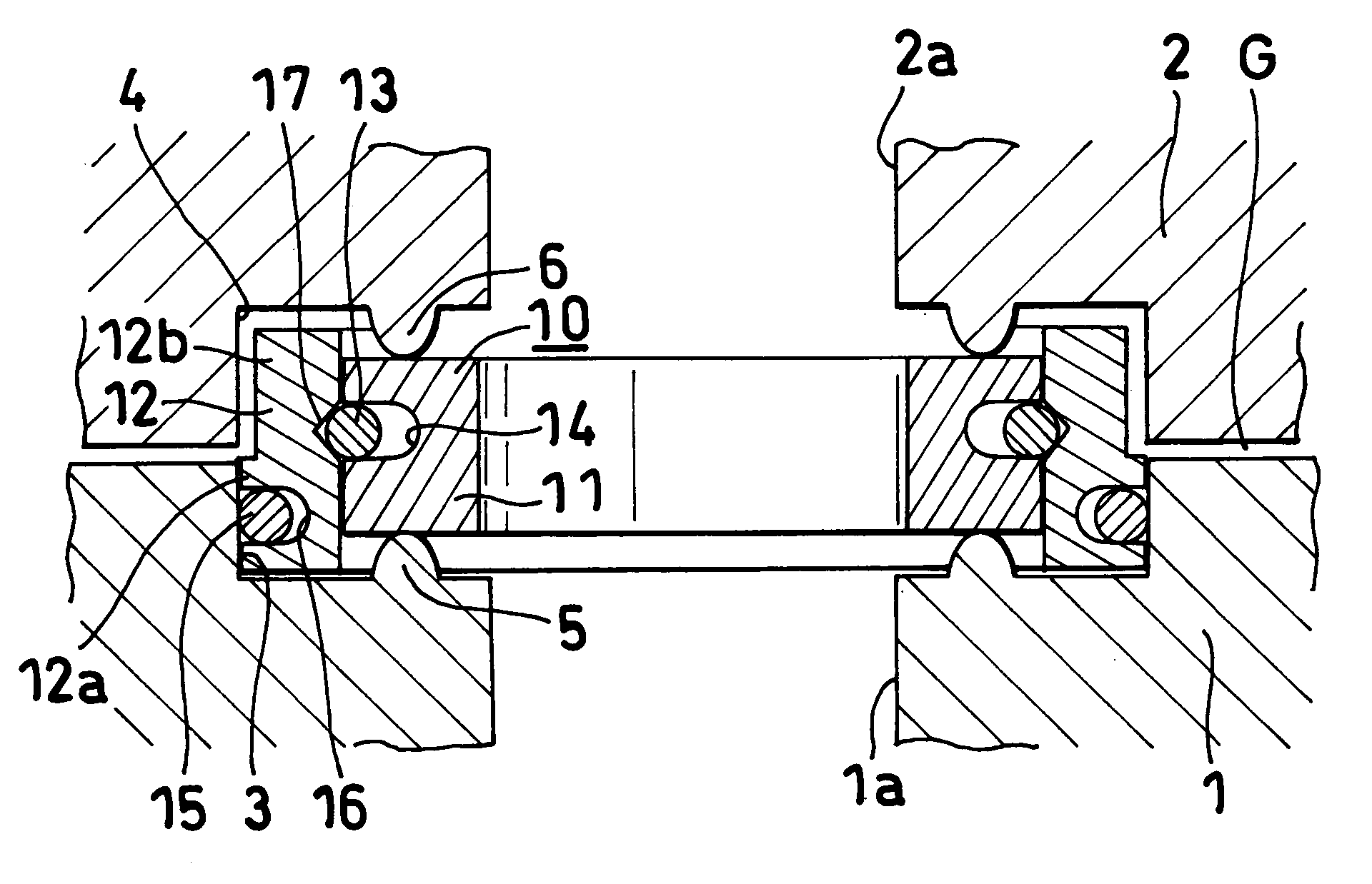
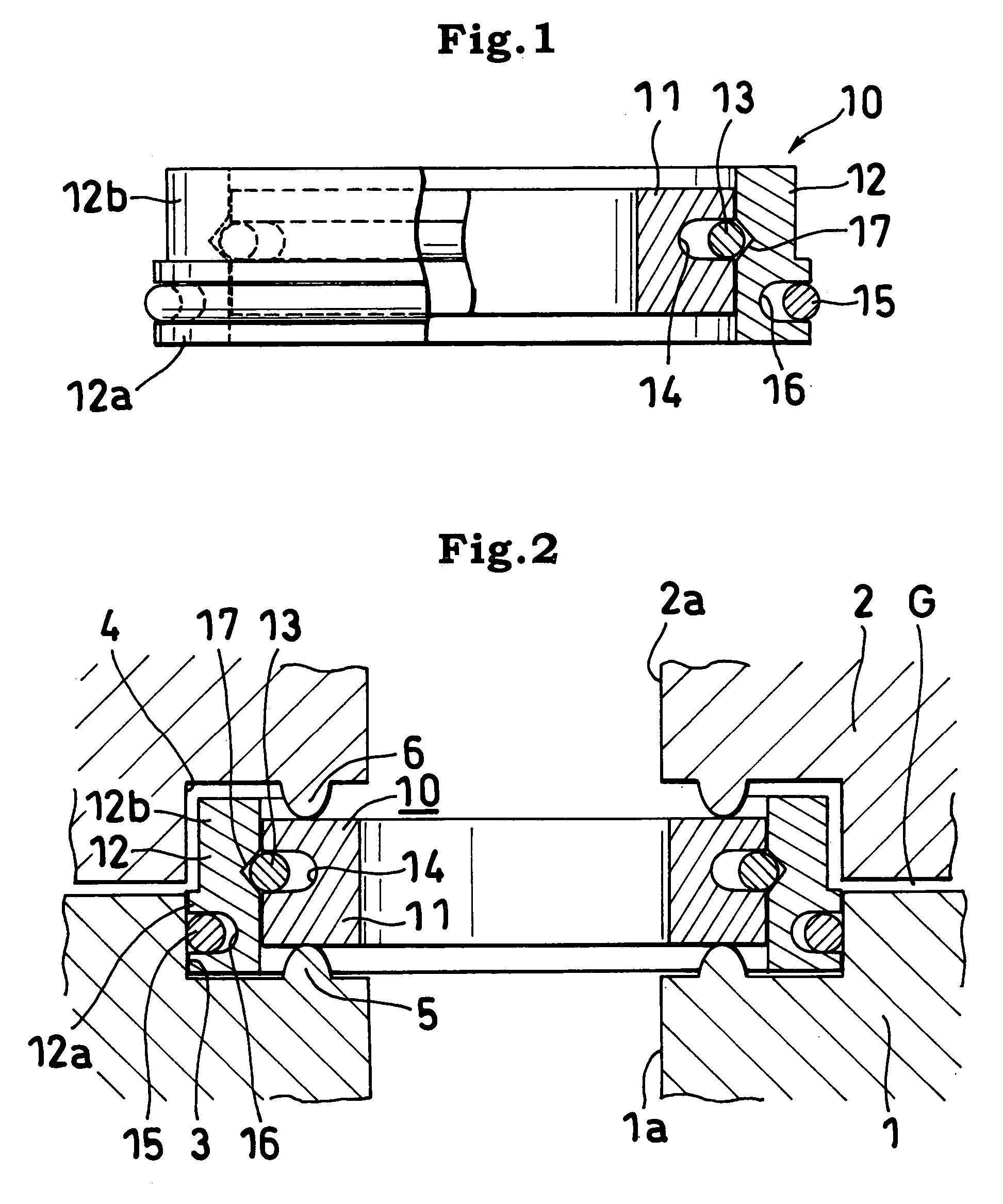
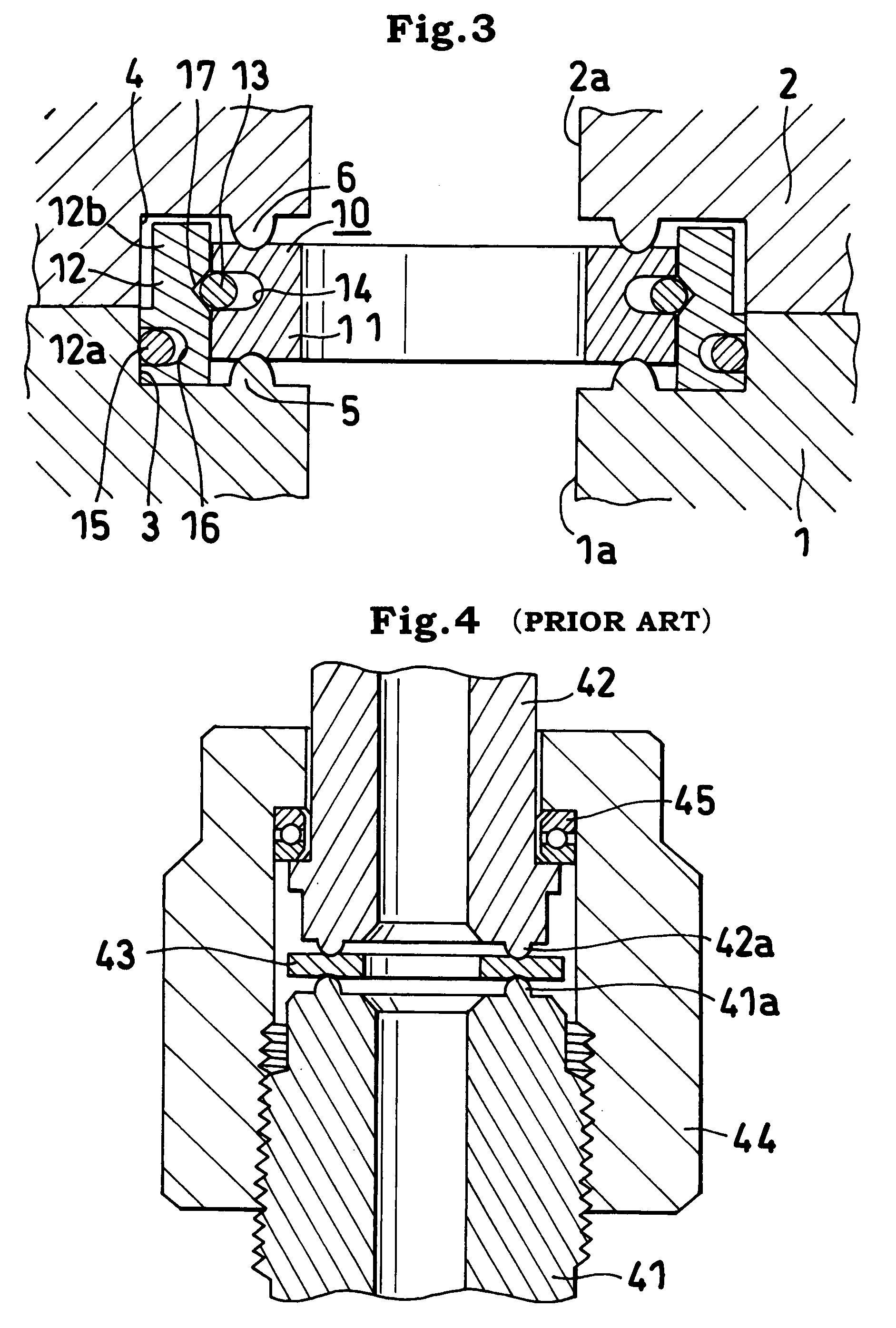
[0016]The fluid coupling of the invention has a structure for joining two coupling members 1, 2 fluid-tightly. The coupling comprises first and second coupling members 1, 2 having respective fluid channels 1a, 2a communicating with each other, an annular gasket 10 interposed between butting end faces of the two coupling members 1, 2, and screw means for fastening the coupling members 1, 2 together. (Although the screw means is not shown, various known means are usable such as the one shown in FIG. 4.)

[0017]Annular recessed portions 3, 4 surrounding the openings of the fluid channels 1a, 2a are formed in the butting end faces of the first and second coupling members 1, 2, respectively, and annular projections 5, 6 are formed in the bottom faces of the recessed portions 3, 4.

[0018]The gasket 10 comprises an annular sealing portion 11 positioned between the annular projections 5, 6 of the coupli...


PUM


Abstract

Two coupling members are provided in respective butting end faces thereof with annular recessed portions surrounding respective fluid channels thereof and having annular projections each formed in a bottom face of the recessed portion. A gasket comprises a sealing portion having an outside diameter smaller than the diameter of the recessed portions and is positioned between the projections of the coupling members, and a guide has an outside diameter permitting the guide to be fitted into the recessed portions and positioned externally of the sealing portion. The butting end faces of the coupling members are movable into contact with each other when the coupling is tightened up properly. The sealing portion has an annular groove formed in an outer periphery thereof, and the sealing portion and the guide are connected together by a snap ring fitted in the annular groove.

Description

TECHNICAL FIELD[0001]The present invention relates to fluid couplings, and more particularly to fluid couplings comprising a gasket which gives predetermined sealing properties to the coupling when deformed.PRIOR ART[0002]FIG. 4 shows a fluid coupling already known. With reference to this drawing, first and second coupling members 41, 42 provided with annular projections 41a, 42a on opposed faces thereof are butted against each other with a gasket 43 interposed therebetween. A cap nut 44 screwed on the first coupling member 41 is tightened up to deform the gasket 43 and give a proper sealing force. Indicated at 45 is a thrust ring for facilitating the rotation of the cap nut 44.[0003]With such a fluid coupling, the proper amount of rotation to be given to the cap nut 44 after the nut is manually tightened is predetermined so as to obtain the proper sealing force by pretightening the nut manually and fully tightening up the nut with a jig. To ensure the proper sealing force, it is al...

Claims


Application Information

Patent Timeline
Patent Type & Authority Patents(United States)
IPC IPC(8): F16L25/00F16J15/02F16L19/03F16J15/06F16J15/10F16J15/12F16L17/00F16L19/00F16L19/02F16L27/08
CPCF16J15/02F16J15/062F16J15/104F16L19/00F16L19/0212F16L19/0218F16L25/0018F16L27/082F16L27/0828Y10S285/917Y10S277/925
Inventor OHMIYAMAJI, MICHIONOJIMA, SHINYAKATSUMI, YUKITOSHINOHARA, TSUTOMU
Owner OHMI
Why Eureka
Try Eureka