
Valve element

a valve element and valve body technology, applied in the field of valve elements, can solve the problems of not producing the desired size of the hole, affecting the flow of pressure medium, etc., and achieve the effect of reliable operation of the valve element and reliably opening

Inactive Publication Date: 2006-12-05
MARIOFF CORP OY
View PDF15 Cites 20 Cited by
  • Summary
  • Abstract
  • Description
  • Claims
  • Application Information

AI Technical Summary

Benefits of technology

The present invention relates to a valve element that can be used in fire extinguishing systems. The valve element includes a main body, an inlet, an outlet, a burst disk, and a piston with a piercing element. The piston has a passage for a pressure medium, and the burst disk is designed to close the passage when unbroken. The invention solves the problem of previous devices where the burst disk could block the passage and cause an obstacle to the flow of pressure medium. The new valve element is leak-proof and reliable, and can be triggered by a control signal to open the passage. The technical effect of the invention is to provide a valve element that can be used in fire extinguishing systems with greater reliability and effectiveness.

Problems solved by technology

A device corresponding to the subject of the invention is known from specification DE 2635076 A. One of the drawbacks of this solution is that the piercing element is returned by the action of pressure back to its original position, so a piece of the burst disk that may have been detached from it by the piercing action may partially block the passage and thus form an obstacle to the flow of pressure medium.
If the piercing movement is for some reason incompletely executed, it will not produce a hole of the desired size.

Method used


Image

  • Valve element
  • Valve element

Examples


Embodiment Construction

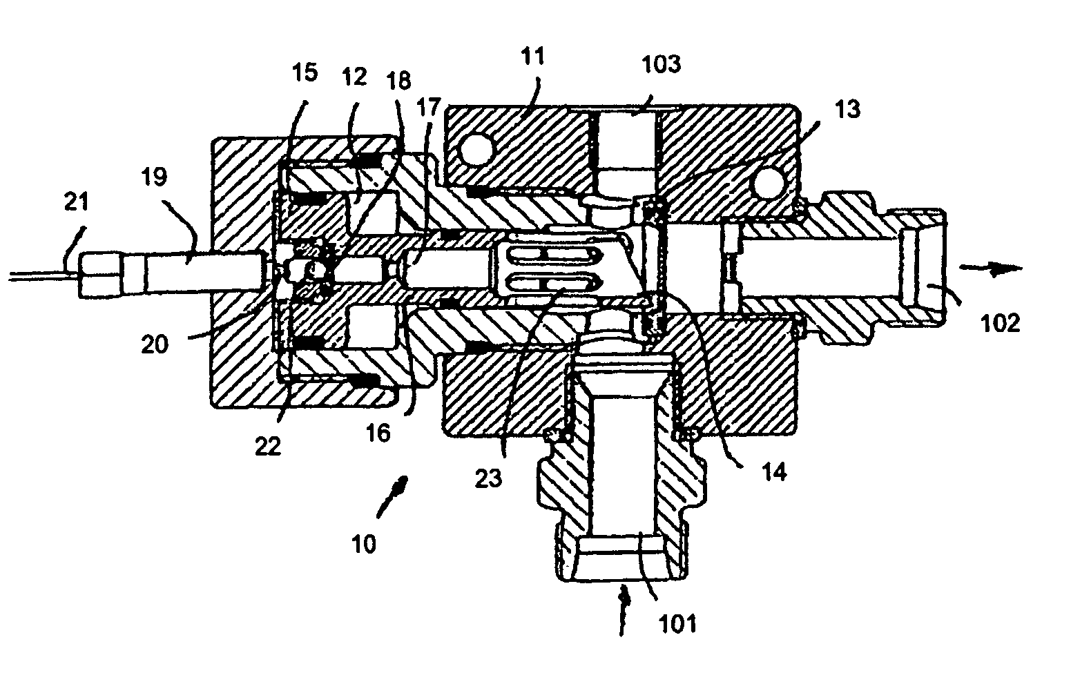
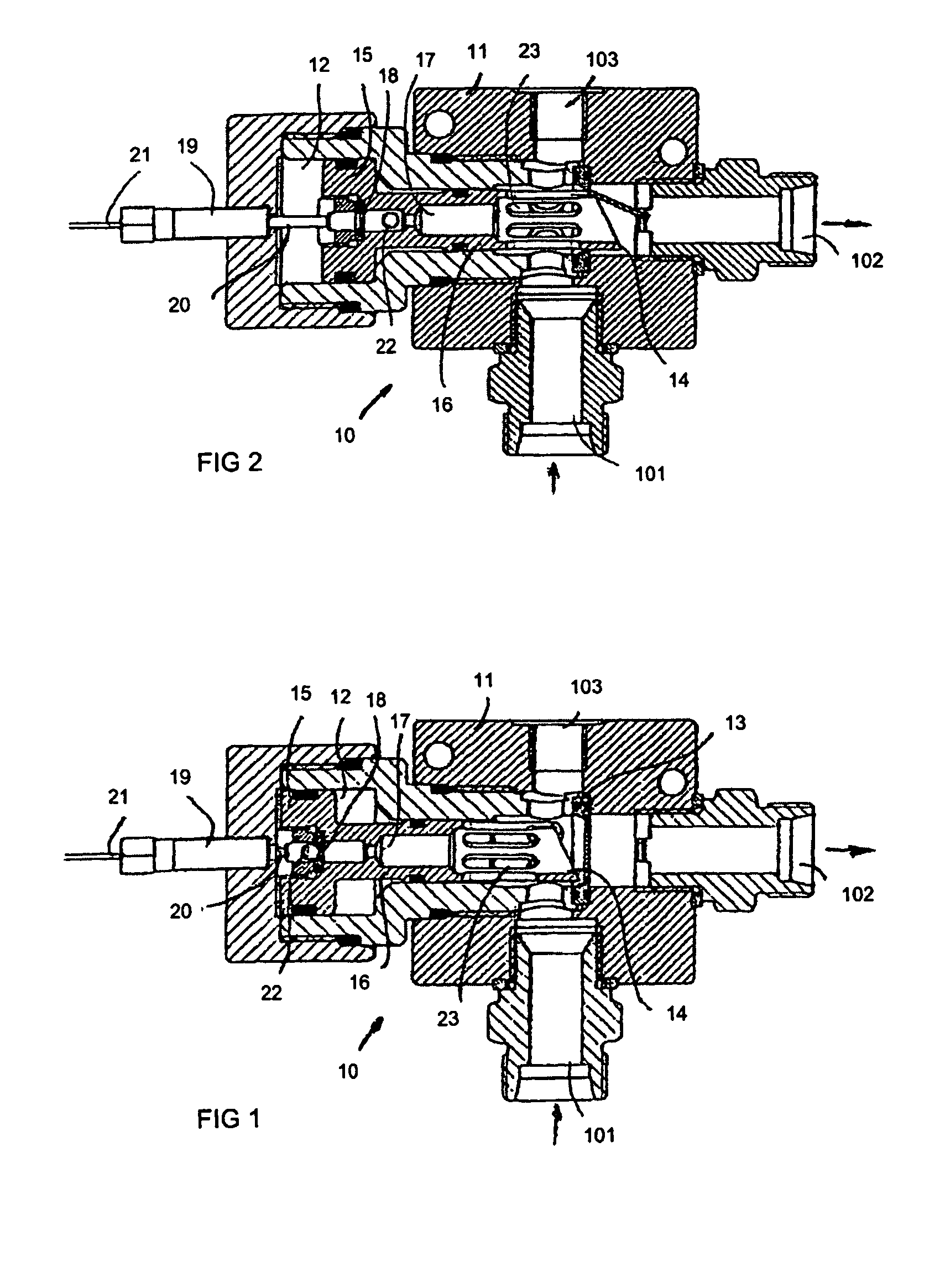
[0010]FIG. 1 presents a valve element according to the invention in standby state. The device comprises a main body 11, which is provided with an inlet 101 connectable to a pressure source and an outlet 102 connectable to an outbound line. Provided between the inlet and the outlet is a burst disk 13 (rupture disk) which, when unbroken, closes the passage from the inlet 101 to the outlet 102. The device also comprises means for piercing the burst disk 13. These means consist of a cylinder-piston combination in which the piston 15 comprises a piercing element 14 formed on it, preferably on the piston rod 16 part. The piston 15 has been arranged to be movable within a cylinder space 12 between a fist position, where the piercing element 14 formed on the piston rod 16 is on the inlet side in relation to the burst disk 13, and a second position, where the piercing element extends at least partially to the outlet side in relation to the burst disk 13.

[0011]The piston is provided with at l...


PUM


Abstract

Valve element (10), comprising a main body, at least one inlet (101) and at least one outlet (102), a passage connecting the inlet and outlet, at least one burst disk (rupture disk) (13) or equivalent, which, when unbroken, closes the passage from inlet to outlet, and a piston element (15) provided with a piercing element (14) or the like for piercing the burst disk. The piston element (15) is provided with a passage (17) for a pressure medium, said passage extending axially through the piston element from one first side to one second side, that the piston element is provided with a second burst disk or equivalent which, when unbroken, closes the passage (17) provided in the piston element.

Description

BACKGROUND OF THE INVENTION[0001]The present invention relates to a valve element as defined in the preamble of claim 1, comprising a main body, at least one inlet and at least one outlet, a passage connecting the inlet and outlet, at least one burst disk (rupture disk) or equivalent, which, when unbroken, closes the passage from the inlet to the outlet, and piston element comprising a piercing element or the like for piercing the burst disk.[0002]A device corresponding to the subject of the invention is known from specification DE 2635076 A. One of the drawbacks of this solution is that the piercing element is returned by the action of pressure back to its original position, so a piece of the burst disk that may have been detached from it by the piercing action may partially block the passage and thus form an obstacle to the flow of pressure medium. In addition, the piercing element has to go completely through the burst disk in order to produce a hole of the desired size in the di...

Claims


Application Information

Patent Timeline
Patent Type & Authority Patents(United States)
IPC IPC(8): F16K17/40A62C35/68A62C35/08A62C13/64A62C13/68
CPCA62C13/64A62C35/68F16K13/04Y10T137/1707Y10T137/1647Y10T137/1767A62C35/08A62C37/08
Inventor SUNDHOLM, GORAN
Owner MARIOFF CORP OY
Learn More