Automatic pool cleaner power conduit including stiff sections

a technology of automatic cleaning and conduit assembly, which is applied in the direction of swimming pools, mechanical equipment, chemistry equipment and processes, etc., can solve the problems of physical interference hinder the cleaner's ability to freely and fully travel through the pool, etc., and achieve the effect of enhancing the visual aspect of the display

Inactive Publication Date: 2006-12-05
HENKIN LABY
View PDF16 Cites 18 Cited by
  • Summary
  • Abstract
  • Description
  • Claims
  • Application Information

AI Technical Summary

Benefits of technology

[0010]The stiff elongate section in accordance with the invention provides a large moment arm assuring the production of sufficient torque around the swivelable means to assure adequate axial swiveling between the cleaner and the power source to thus avoid the formation of persistent coils and / or knots.
[0013]In operation, as the cleaner travels along a substantially random path through the pool, it pulls the conduit and continually reorients the stiff members relative to one another. This action produces a dynamic display of randomly oriented essentially straight line segments (i.e., the stiff elongate members) which is visually interesting and pleasing. The visual aspects of the display can be enhanced by illuminating the sections, e.g., by providing an illumination source on each stiff section. Such sources can comprise an electrically energizable element such as a bulb, LED, etc., or a light energizable surface such as photoluminesent material mounted on the stiff section exterior surface which absorbs light energy during daylight and glows after dark.

Problems solved by technology

Regardless of the energy form used, the flexible conduit can on occasion physically interfere with and hinder the cleaner's ability to freely travel through the pool.
Despite the aforementioned efforts to prevent the cleaner from engaging the conduit and efforts to facilitate conduit axial flexibility and axial swivelability, in practice, a typical conduit over an extended period of operation may develop persistent coils and / or knots which can hinder the cleaner's ability to freely and fully travel throughout the pool.

Method used


Image

  • Automatic pool cleaner power conduit including stiff sections
  • Automatic pool cleaner power conduit including stiff sections
  • Automatic pool cleaner power conduit including stiff sections

Examples


Embodiment Construction

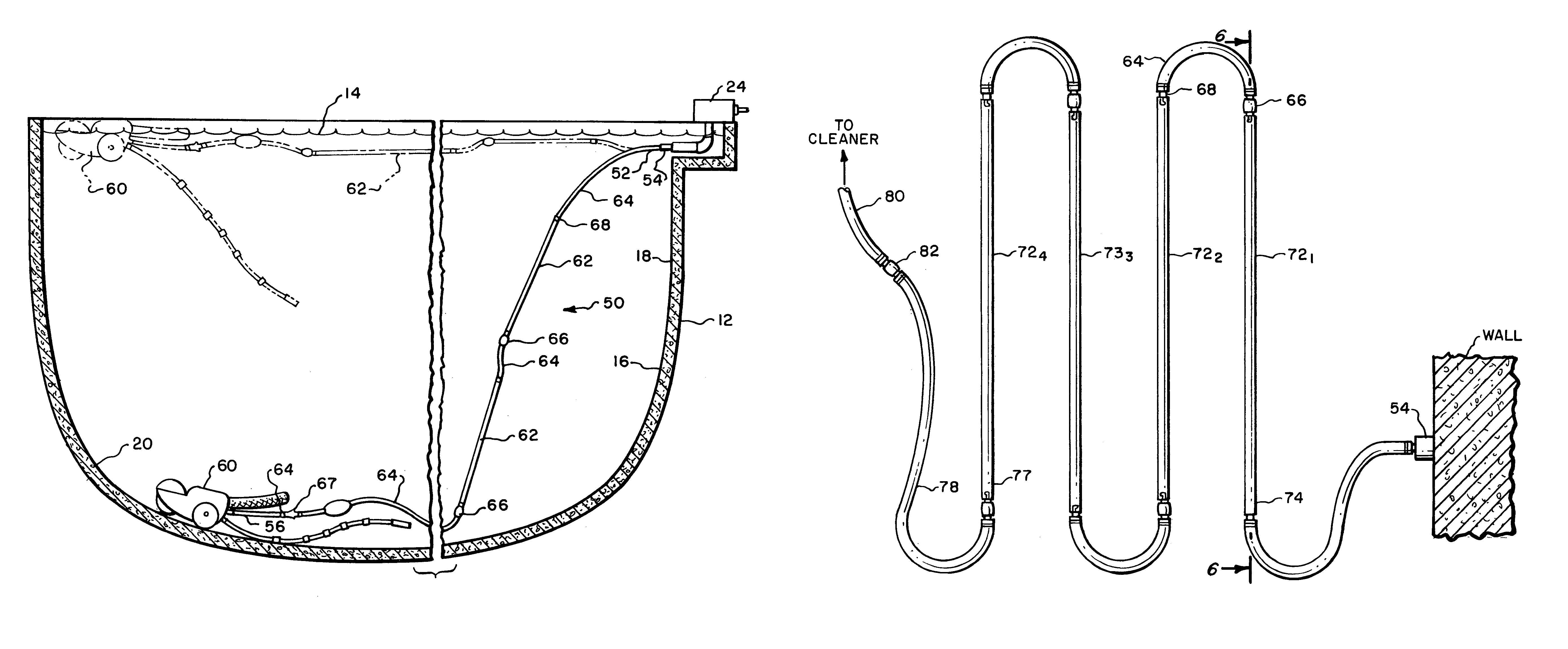
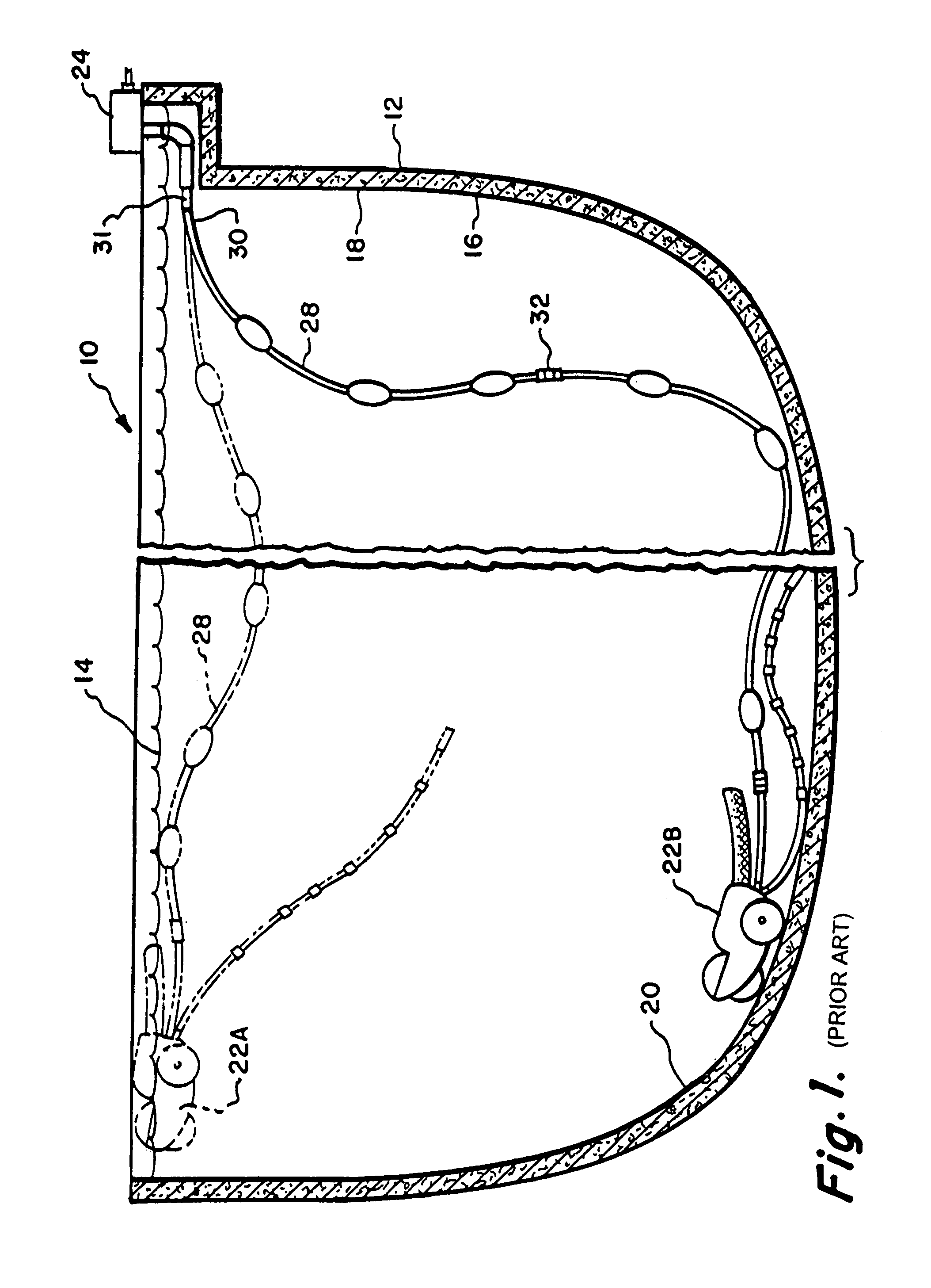
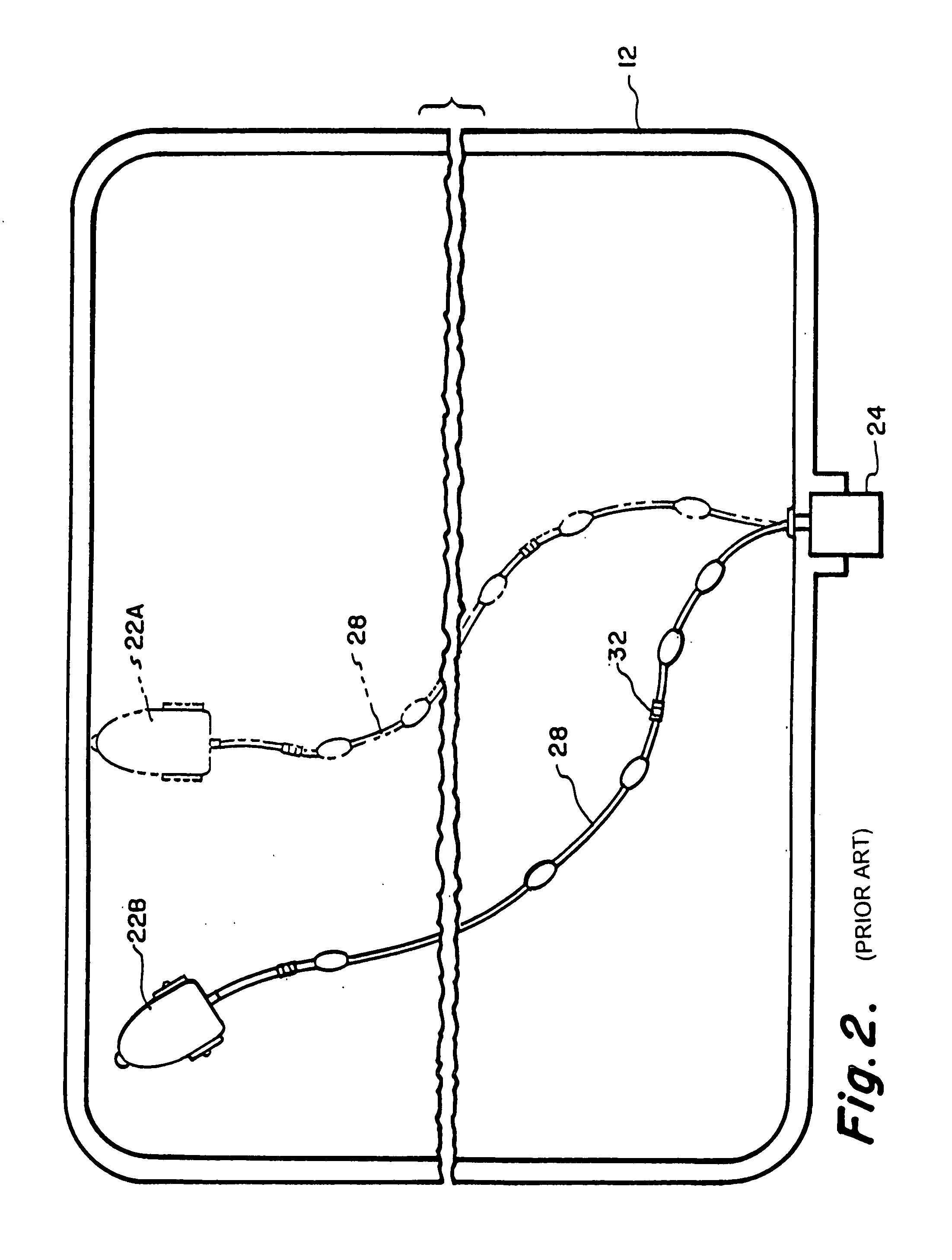
[0022]Attention is initially directed to FIGS. 1 and 2 which schematically illustrate a conventional water pool 10 contained by a containment wall 12. The pool 10 defines a water surface 14 and the wall 12 defines a wall surface 16 including side portions 18 and a bottom or floor portion 20.

[0023]Many automatic pool cleaners are described in the literature which include a cleaner body for traveling through a pool for cleaning a pool's water surface 14 and / or wall surface 16. FIGS. 1 and 2 schematically depict an exemplary pool cleaner body 22 (shown in dashed line 22A) configured to travel along the water surface 14 and an exemplary pool cleaner body 22 (shown in solid line 22B) configured to travel along the wall surface 16. It should be understood that the cleaner bodies (hereinafter, generally referred to as “cleaners”) schematically represented at 22A and 22B can comprise separate alternative physical units or the same physical unit operating in different modes; i.e., in a water...


PUM


Abstract

An improved power conduit for use with automatic pool cleaners particularly configured to avoid the formation of persistent coils and / or knots. Embodiments in accordance with the invention are characterized by the use of at least one axially stiff elongate member together with axially flexible and axially swivelable means for coupling said stiff member between a stationary power source fitting and a cleaner. The axially flexible and axially swivelable means can be implemented in a variety of ways, e.g., a flexible elongate hose member and a swivel coupling.

Description

RELATED APPLICATION[0001]This application is a continuation of International Application PCT / US03 / 032639 filed on 15 Oct. 2003 which claims priority based on U.S. Provisional Application No. 60 / 424,786 filed on 7 Nov. 2002. This application claims priority based on both PCT / US031032639 and on U.S. 60 / 424,786.FIELD OF THE INVENTION[0002]This invention relates generally to a pool cleaner having a power conduit coupled thereto for enabling the cleaner to travel through a water pool for cleaning the water surface and / or the wall surface of a containment wall containing the water pool. More particularly, the present invention is directed to an improved conduit assembly for coupling a power source (e.g., positive pressure fluid and / or negative pressure fluid and / or electric) to a cleaner for supplying energy for propulsion and / or cleaning.BACKGROUND OF THE INVENTION[0003]Automatic cleaners configured to travel through a water pool for cleaning the pool water surface and / or containment wal...

Claims


Application Information

Patent Timeline
Patent Type & Authority Patents(United States)
IPC IPC(8): F16L9/12E04HE04H1/00E04H4/16H02G3/04
CPCE04H4/1654
Inventor HENKIN, MELVYN L.LABY, JORDAN M.
Owner HENKIN LABY
Why Eureka
Try Eureka