Image correction device

a technology of image correction and image reader, which is applied in the direction of instruments, digitally marking record carriers, electrographic processes, etc., can solve the problems of deteriorating image quality, inaccurate image correction, and inability to obtain optimal image correction information of combined image readers and image forming apparatuses, etc., to suppress distortion caused by devices and high-quality image formation

Inactive Publication Date: 2006-12-05
MINOLTA CO LTD
View PDF8 Cites 6 Cited by
  • Summary
  • Abstract
  • Description
  • Claims
  • Application Information

AI Technical Summary

Benefits of technology

[0008]The invention provides an image correction device capable of supporting high quality image formation and suppressing distortion caused by the device

Problems solved by technology

However, since correction methods used in conventional image transmission devices utilize image information relating to individual image readers or image forming apparatuses, optimum image correction information of combined image readers and image forming apparatuses is not obtained, and accurate image correction is not achieved.
A further disadvantage arises in that image quality deteriorates when discrepancies occur in the image correction information due to changes over time and mechanical differences betw

Method used


Image

  • Image correction device
  • Image correction device
  • Image correction device

Examples


Embodiment Construction

[0032]The preferred embodiments of the invention are described hereinafter by way of specific examples with reference to the accompanying drawings.

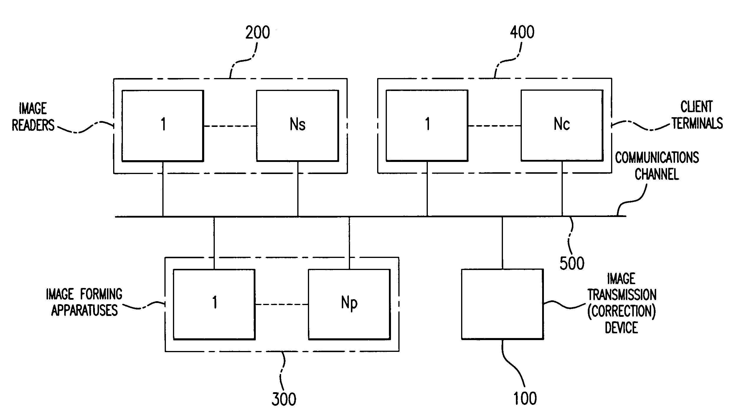
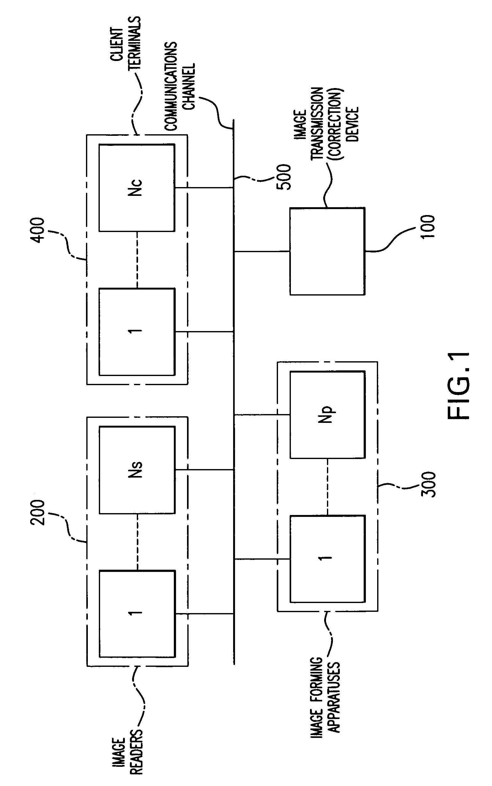
[0033]FIG. 1 shows the overall construction of an example of the main system. This main system comprises an image transmission device 100, a plurality of image readers 200 numbered 1 through Ns, a plurality of image forming apparatuses 300 numbered 1 through Np, a plurality of client terminals 400 numbered 1 through Nc, and a communications channel 500. Each of devices 100, 200, 300 and 400 are connected via communications channel 500 so as to be capable of sending and receiving image information and control information over communications channel 500.

[0034]Image reader 200 is a scanner or digital camera, for example, for converting optical data of a specific subject to electrical signals to be transmitted as digital image data to another device via communications channel 500.

[0035]Image forming apparatus 300 is a printer, for example, fo...


PUM


Abstract

An image correction device for use in an image forming system which is connectable to a plurality of image readers and image forming apparatuses, the image correction device is capable of suppressing distortion in the image forming system by using optimum image correction information corresponding to mechanical differences and changes over time in the plurality of image readers and image forming apparatuses, the image correction device includes a discriminating device for discriminating the image readers from the image forming apparatuses which are connected to the image correction device, memory means for storing correction data relating to combinations of the image readers and image forming apparatuses and data correction means for correcting image data output from an image reader using the correction data relating to a specific combination of image reader and image forming apparatus and for outputting the corrected data to an image forming apparatus.

Description

CROSS-REFERENCE TO RELATED APPLICATIONS[0001]This application is based on Patent Application No. HEI 10-40062 filed in Japan, the content of which is hereby incorporated by reference.FIELD OF THE INVENTION[0002]The invention relates to an image correction device and a medium for storing an image correction program. Specifically, the invention relates to a device for correcting images and a medium for storing a program for correcting images in a system including an image transmission device and a plurality of image readers, a plurality of image forming apparatuses or a plurality of terminals connected together via a communications line.BACKGROUND OF THE INVENTION[0003]In a conventional image forming apparatus and image reader, when an image is read optically and printed on a paper sheet, the printing results vary due to changes over time and mechanical differences of the image forming apparatus and image reader. When these variations occur, it becomes necessary to perform image corre...

Claims


Application Information

Patent Timeline
IPC IPC(8): H04N1/00G03G15/00H04N1/21H04N1/40H04N1/407
CPCG03G15/50H04N1/00002H04N1/00007H04N1/00023H04N1/00031H04N1/00045H04N1/00087H04N1/0009H04N1/32507H04N1/32523H04N1/40H04N1/40006H04N1/4078
Inventor YOSHIMURA, TOMONARI
Owner MINOLTA CO LTD
Why Eureka
Try Eureka