Image forming apparatus to which a sheet discharge device can be detachably mounted

a technology of image forming apparatus and discharge device, which is applied in the direction of electrographic process, instruments, transportation and packaging, etc., can solve the problems of reducing the time required from supplying a recording medium to discharge thereof, and sacrificing the suitable stacking of the recording medium

Active Publication Date: 2006-12-05
CANON KK
View PDF3 Cites 13 Cited by
  • Summary
  • Abstract
  • Description
  • Claims
  • Application Information

AI Technical Summary

Benefits of technology

[0010]The present invention has been made in light of the above-described problems, and accordingly it is an object thereof to provide an image forming apparatus wherein the time required from supplying a recording medium to discharge thereof is reduced as much as possible without sacrificing suitable stacking of the recording medium even in the event of reversing the recording medium on which an image has been formed before discharging.
[0011]It is another object of the present invention to provide an image forming apparatus wherein control can be effected to change the discharge speed of the recording medium depending on whether a sheet discharge device has been connected to the image forming apparatus, thereby transporting recording sheets at a suitable speed according to whether or not a sheet discharge device has been connected.
[0012]It is a further object of the present invention to provide an image forming apparatus wherein the discharge speed for discharging the recording medium from a first transporting path and a second transporting path to a recording sheet stacking unit, and also setting a reverse transporting speed which is the speed of reverse transportation of the recording medium in the second transporting path till a reversal position where the recording medium is reverse, which is faster than the discharge speed, whereby the time required from supplying a recording medium to discharge thereof is reduced as much as possible without sacrificing suitable stacking of the recording medium even in the event of reversing the recording medium on which an image has been formed before discharging.

Problems solved by technology

However, there is the problem that discharging sheets face-up at all times means that multiple copies made will be stacked on the discharge tray in the reverse order to that desired, and a stack of copies in the order in which the copies were made cannot be received by the user.
However, the transporting distance of sheets is longer with cases wherein the sheets are reversed with the reversal mechanism, in comparison with cases wherein sheets are not reversed at the reversal mechanism and discharged face-up.

Method used


Image

  • Image forming apparatus to which a sheet discharge device can be detachably mounted
  • Image forming apparatus to which a sheet discharge device can be detachably mounted
  • Image forming apparatus to which a sheet discharge device can be detachably mounted

Examples


first embodiment

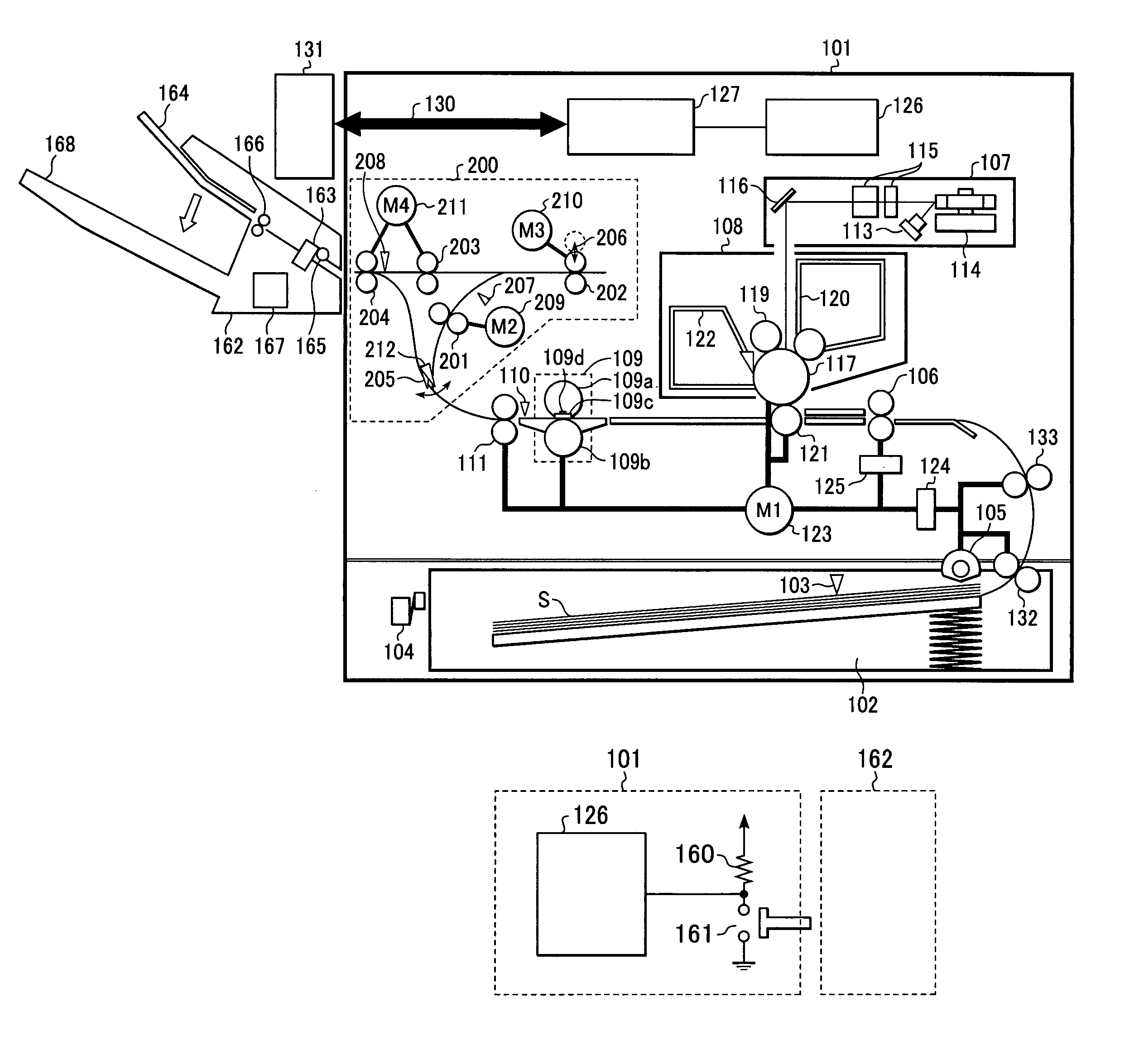
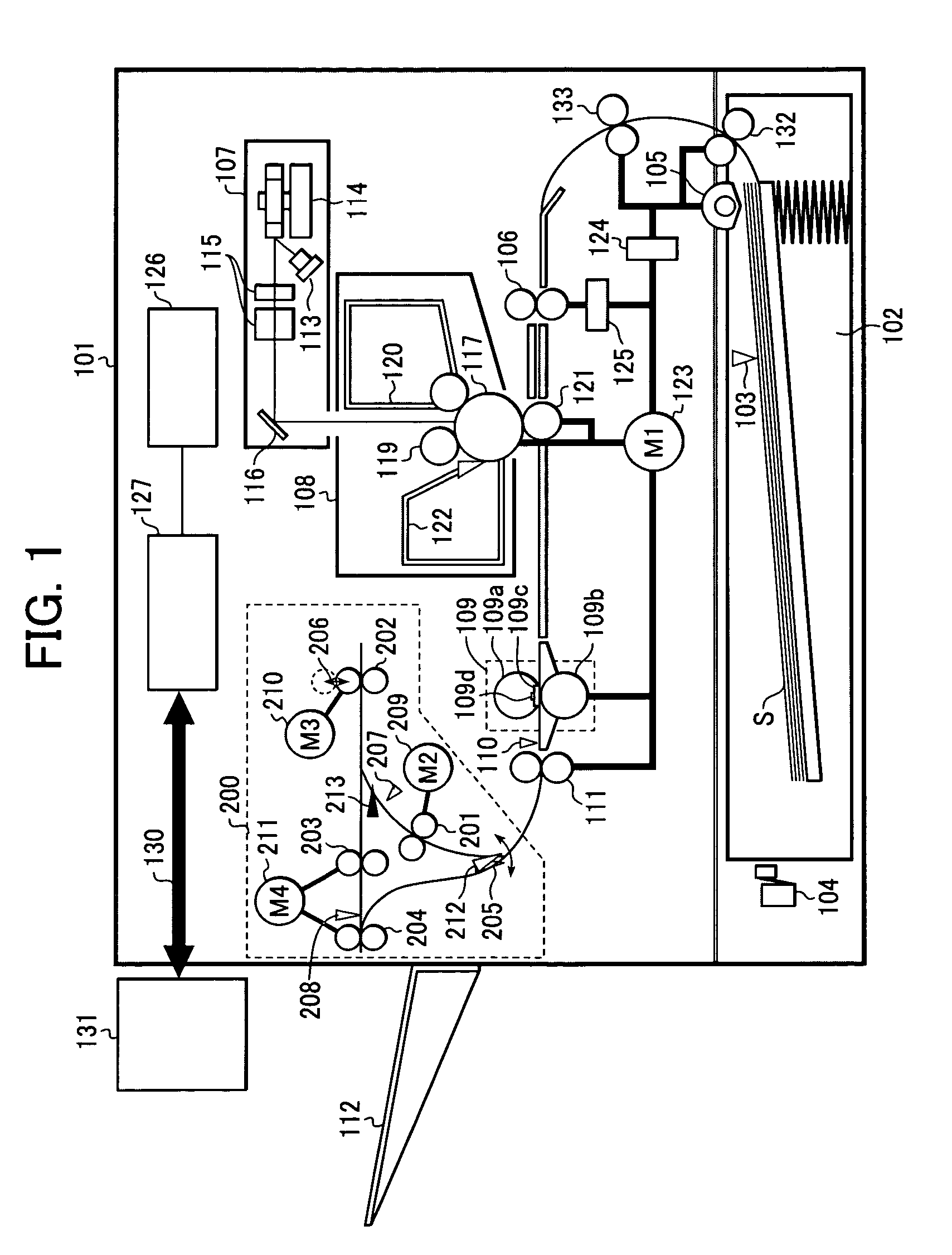
[0037]FIG. 1 is a cross-sectional view illustrating the configuration of a laser beam printer using an electrophotographic process. A laser beam printer main unit 101 (hereafter referred to simply as “main unit 101”) comprises a cassette 102 for storing recording sheets A serving as a recording medium, a cassette sheet sensor 103 for detecting whether or not recording sheets S are within the cassette 102, a cassette size sensor 104 for detecting the size of the recording sheets S within the cassette 102 (made up of multiple micro-switches), a sheet supplying roller 105 for separating and supplying the recording sheets S one at a time from the cassette 102, and a feed roller 132 for transporting recording sheets S supplied from the sheet supplying roller 105.

[0038]In the drawing, reference numeral 106 denotes a resist roller pair for transporting the recording sheets S transported by the feed roller 132 and an intermediate roller 133.

[0039]Reference numeral 107 denotes a laser scanne...

second embodiment

[0106]Next, a second embodiment of the present invention will be described. This second embodiment is a modification of the first embodiment, and components not described in particular here, including the configuration of the main unit 101, are to be understood to be of the same configuration as described in the first embodiment, and also to operate in the same manner.

[0107]In the first embodiment, the engine controller 126 maintained the speed of the main motor 123 at a constant speed so as to effect transportation at a speed of V1 (mm / sec) until the recording sheet S supplied from the cassette 102 within the main unit 101 reaches the fixing unit 109. Conversely, with the second embodiment, the engine controller 126 selects between an action of maintaining transportation at the speed of V1 (mm / sec) until the recording sheet S supplied from the cassette 102 within the main unit 101 reaches the fixing unit 109, and an action wherein the transportation speed is half, i.e., V1 / 2.

[0108]...

third embodiment

[0122]Next, a third embodiment of the present invention will be described. This third embodiment is a modification of the first embodiment, and components not described in particular here, including the configuration of the main unit 101, are to be understood to be of the same configuration as described in the first embodiment, and also to operate in the same manner.

[0123]FIGS. 12A through 12C are diagrams illustrating the transportation state of consecutively transporting recording sheets S with the reverse transporting unit 200.

[0124]In FIG. 12A, in the event that a recording sheet S1 is to be transported through the FD transporting path, a1 +a2 (mm) is required for transporting the trailing edge of the recording sheet S1 from the reference position point D to the reversal position point E, and a2+a3+SL (mm) is required for the trailing edge of the recording sheet S1 at the point E to further switch directions from the transportation direction e to the transportation direction f a...


PUM


Abstract

An image forming apparatus is provided which includes an image formation unit for forming images on a recording medium; a first transporting path for discharging a recording medium to a sheet discharge device; a longer second transporting path for reversing the transportation direction of the recording medium; a transporting path switching unit for switching between the first transporting path or the second transporting path; a setting unit for setting the discharge speed for discharging the recording medium from the first and second transporting paths to a recording sheet stacking unit, and also setting the reverse transportation speed; and a determining unit for determining whether or not the sheet discharge device has been connected to the image forming apparatus; wherein the setting unit sets a first discharge speed slower than the reverse transportation speed in the event that the sheet discharge device has not been connected, and otherwise sets a faster second discharge speed.

Description

BACKGROUND OF THE INVENTION[0001]1. Field of the Invention[0002]The present invention relates to an image forming apparatus.[0003]2. Description of the Related Art[0004]There have been conventionally known image forming apparatuses which use electrophotography and so forth to form images on recording media. Of these, with compact photocopiers in particular, in the event that multiple copies are consecutively made on recording media (recording sheets), the recording media with images formed on one side is generally discharged onto a stacking tray disposed at one end of the image forming apparatus in a face-up manner, that is to say, with the side of the sheet on which the image has been formed facing upwards.[0005]Face-up discharging photocopiers are advantageous in that users can readily recognize images formed on the recording media, and in that the height of the apparatus can be suppressed even in the event that an image reading device for reading originals is disposed on top of t...

Claims


Application Information

Patent Timeline
Patent Type & Authority Patents(United States)
IPC IPC(8): G03G15/00B41J29/38B65H5/06B65H29/20B65H29/58B65H29/60B65H43/00G03G15/23G03G21/14
CPCG03G15/234G03G15/6529
Inventor KITAMURA, TOSHIFUMI
Owner CANON KK
Why Eureka
Try Eureka