Electric power plant general control system

a general control system and power plant technology, applied in the direction of computer control, process and machine control, instruments, etc., can solve the problems of increasing the number of necessary persons, increasing the load of operators, and deteriorating the operation

Inactive Publication Date: 2006-12-05
KK TOSHIBA
View PDF19 Cites 6 Cited by
  • Summary
  • Abstract
  • Description
  • Claims
  • Application Information

AI Technical Summary

Benefits of technology

[0035]According to this aspect of the present invention, even in a case where a power generating unit of so-called full automatic type where all of auxiliaries are automatically controlled by a unit computer and a power generating unit whose all auxiliaries are controlled manually by an operator with an operation board, a full automatic power generating unit and a power generating unit whose all auxiliaries are controlled manually by an operator with an operation board are able to be controlled generally from a concentrated operation room because a mock-up portion corresponding to a sequencer portion provided in the automatic control system is provided in the general automation computer of the concentrated operation room and the center-site linkage support terminal unit outputs an operation command contents to an operator to input an operation result.

Problems solved by technology

However, there still remains a tendency that number of necessary persons increases in proportion to the scale of electric power plant (number of power generating units) because the operation control form per each power generating unit still comes to stay incorrigibly.
However, even in the case where such a latest general control system for electric power plants is actually introduced, all power generating units are not constructed newly but some existing power generating units are combined with new units in most cases.
This leads to increment of the operator's load or deterioration of operating effectiveness.

Method used


Image

  • Electric power plant general control system
  • Electric power plant general control system
  • Electric power plant general control system

Examples


Embodiment Construction

[0048]Embodiments of the present invention will be explained hereinafter referring to the drawings. For elements common to or similar to the conventional technologies, or elements common to or similar to each other are denoted by the same marks and repeated explanations thereof will be avoided.

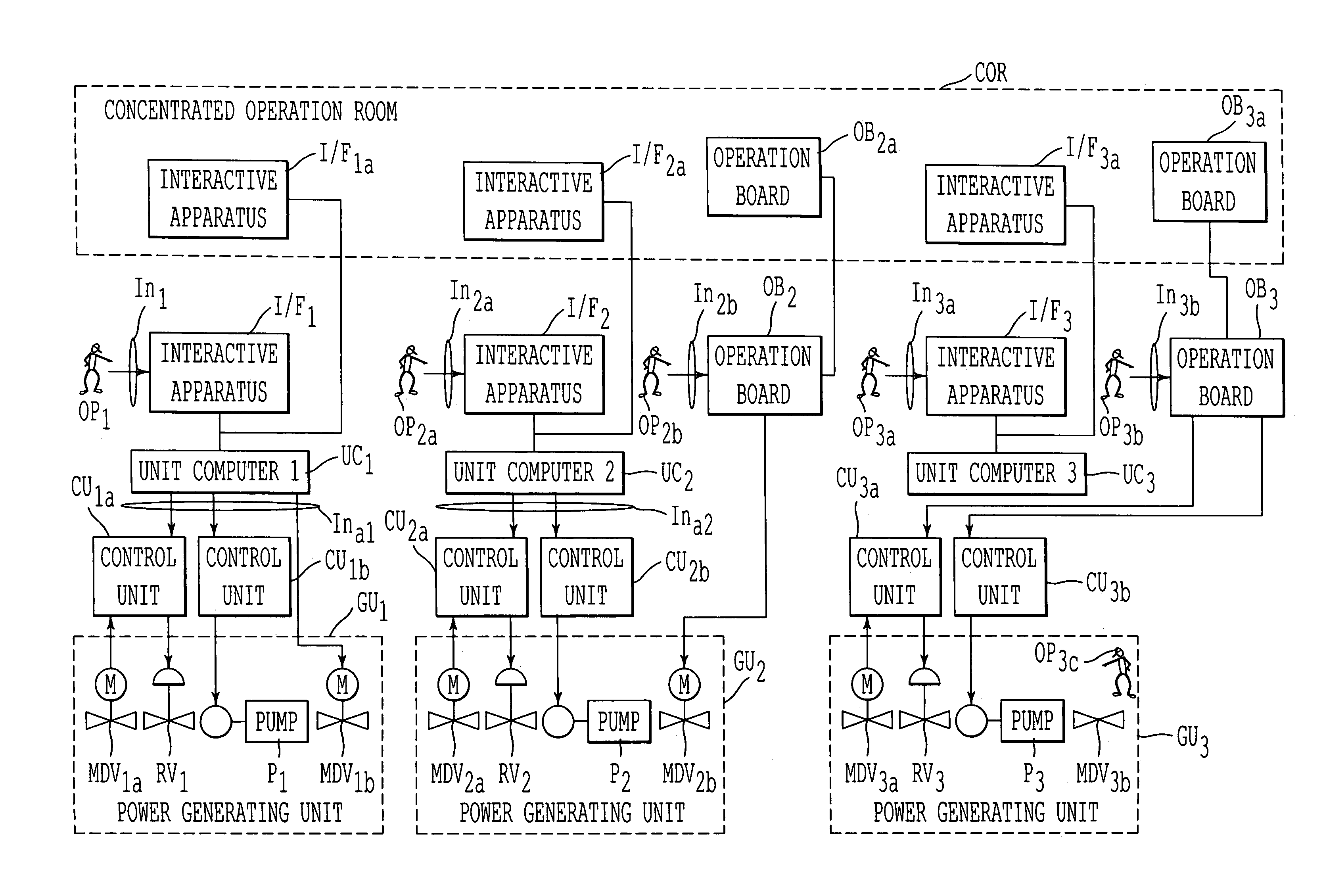
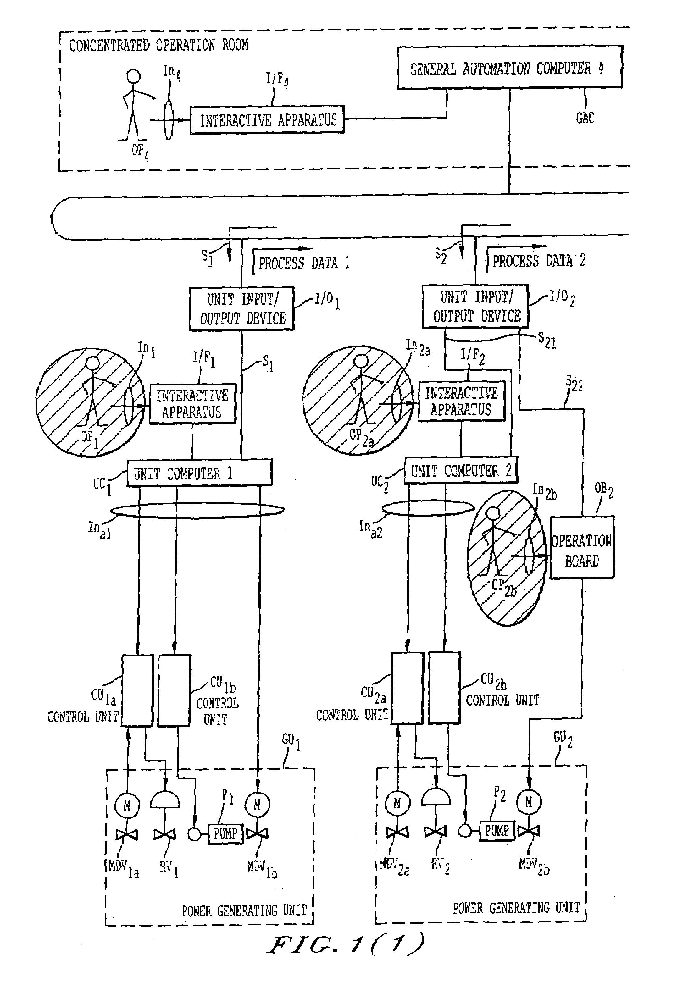
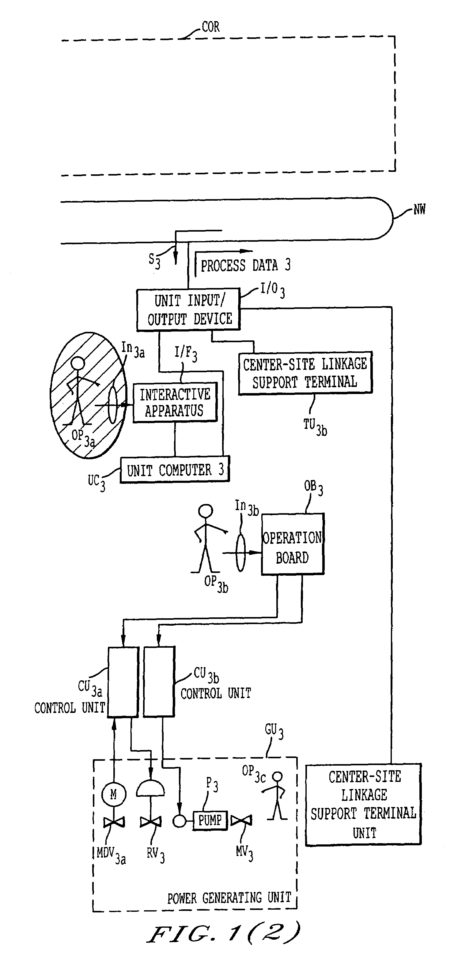
[0049]FIG. 1 is a system configuration diagram showing an embodiment of the electric power plant general control system according to the present invention.

[0050]In the electric power plant general control system shown in FIG. 1, the interactive apparatuses I / F1a, I / F2a, I / F3a and the operation boards OB2a, OB3a in FIG. 8 are taken away from the concentrated operation room COR, whereas a general automation computer GAC having an interactive apparatus I / F4 is newly equipped instead. Then the general automation computer GAC is connected with a network NW newly laid down for general automation.

[0051]On the other hand, unit input / output devices I / O1, I / O2 and I / O3 are provided between unit computer...


PUM


Abstract

An electric power plant general control system for controlling power generating units. A generating unit (GU2) can operate part of the auxiliaries based on an automation command outputted from a unit computer (UC2) having a sequence function portion. The generating unit operates the remaining part of the auxiliaries based on an operation command outputted from an operation board (OB2) without a sequence function portion, the operation board disposed separately from the unit computer. A general automation computer (GAC) is connected with an upper system of the unit computer, and an operator command is inputted from an interactive apparatus (I / F4). The general control system is provided with a mock-up portion (Moc) equivalent to the sequence function portion disposed on the side of the auxiliaries controlled by the automation command outputted from the unit computer. The operation signal from the general automation computer is outputted to the unit computer and the operation board.

Description

FIELD OF THE INVENTION[0001]The present invention relates to an electric power plant control system controlling generally operation of a plurality of power generating units.BACKGROUND OF THE TECHNOLOGY[0002]Operation of electric power plants has ever been carried out for each individual power generating unit in an electric power plant. For example, each power generating unit is allotted with a group of operators including 5 to 6 persons (watchkeepers) with work shift so as to cope quickly with occurrence of abnormal situation of the power generating unit. Automation of the operation of electric power plants has progressed with times, so that number of maintenance workers for the power generating unit can have been surely cut down.[0003]However, there still remains a tendency that number of necessary persons increases in proportion to the scale of electric power plant (number of power generating units) because the operation control form per each power generating unit still comes to s...

Claims


Application Information

Patent Timeline
Patent Type & Authority Patents(United States)
IPC IPC(8): G06F17/00G06F19/00G05B23/02
CPCG05B15/02
Inventor TANAKA, TOSHIHIKOFUKUDA, HIROSHIMURATA, JINYAMADA, TOSHIHIRO
Owner KK TOSHIBA
Why Eureka
Try Eureka