Non-inertial release safety restraint belt buckle systems

a safety restraint and non-inertial release technology, applied in the direction of fastenings, garment fasteners, press-button fasteners, etc., can solve the problem that both latching mechanisms cannot be simultaneously released, and achieve the effect of reducing manufacturing costs and reducing the risk of component failur

Inactive Publication Date: 2006-12-12
BENEDICT CHARLES E
View PDF9 Cites 5 Cited by
  • Summary
  • Abstract
  • Description
  • Claims
  • Application Information

AI Technical Summary

Benefits of technology

[0037]It is the primary object of the present invention to provide safety restraint systems for use with lap and shoulder belts associated with vehicles which include buckles having latching mechanisms which can not be released by inertial forces applied to the components thereof such as caused during vehicle accidents, including rollovers.
[0038]It is yet another object of the present invention to provide latching and locking mechanisms for seat belt restraint systems which are operative in accordance with Newtonian Laws of Physics to the effect that for every action there is an equal and opposite reaction so that a latch plate of one of the systems can not be released from a buckle unless oppositely directed forces are applied to oppositely biased latching mechanisms associated with each restraint system.
[0039]It is also an object of one of the embodiments of the present invention to provide latching and locking mechanisms for seat belt restraint systems wherein an inadvertent or accidental application of force to one of a pair of release push buttons associated therewith cannot cause the premature release of a latch plate and wherein such accidental application of force in effect supplies a greater force to insure that one of the two latching mechanisms associated therewith is retained in a locked position.
[0040]It is another of the present invention to provide non-inertial release restraint buckles for use in seat belt restraining systems of the type used in automotive vehicles and the like wherein latching mechanisms associated with each buckle are structured from a minimal number of moving components to thereby reduce the risk of component failure while decreasing manufacturing costs.

Problems solved by technology

Thus, both latching mechanisms cannot be simultaneously released by the application of inertial forces which may be applied against the buckles.

Method used


Image

  • Non-inertial release safety restraint belt buckle systems
  • Non-inertial release safety restraint belt buckle systems
  • Non-inertial release safety restraint belt buckle systems

Examples


Embodiment Construction

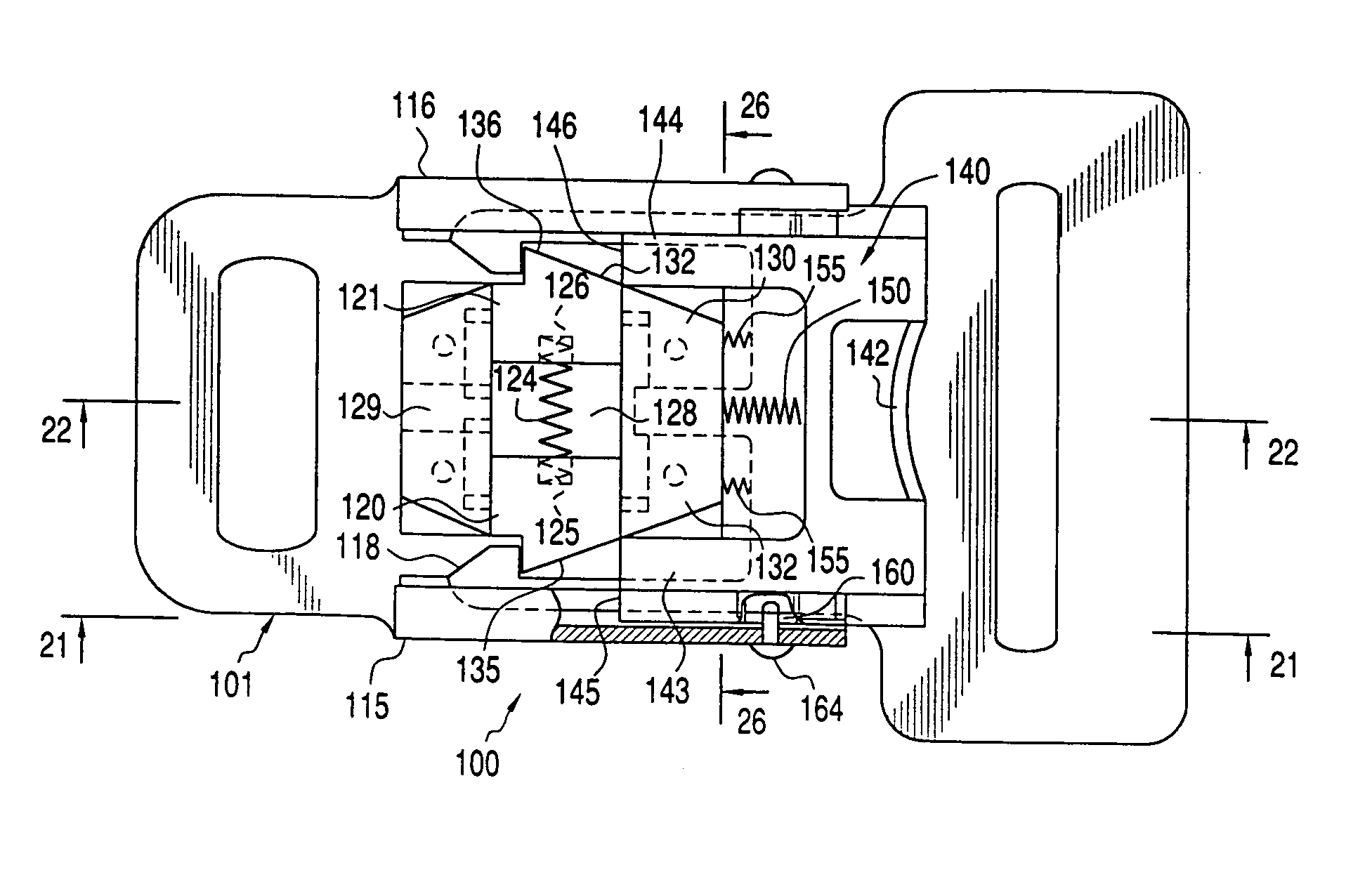
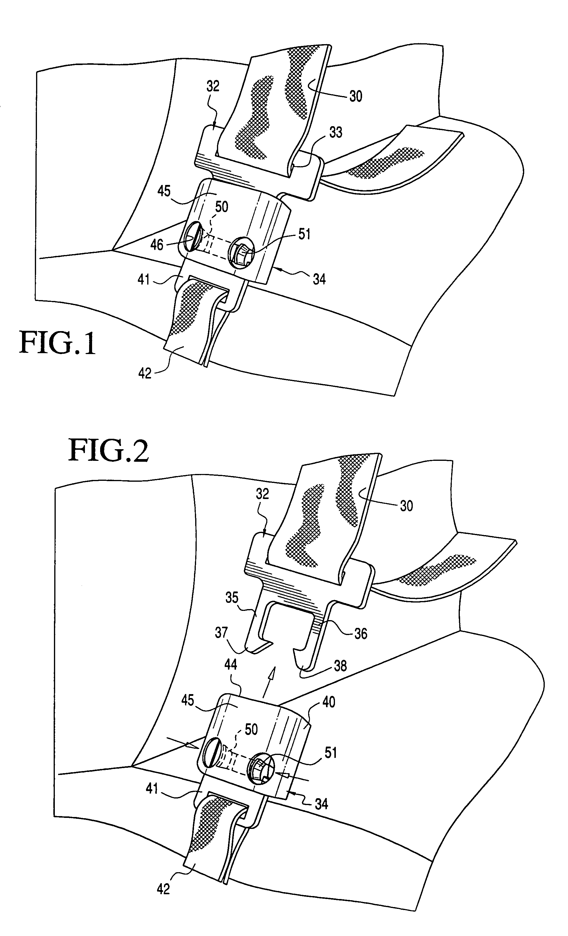
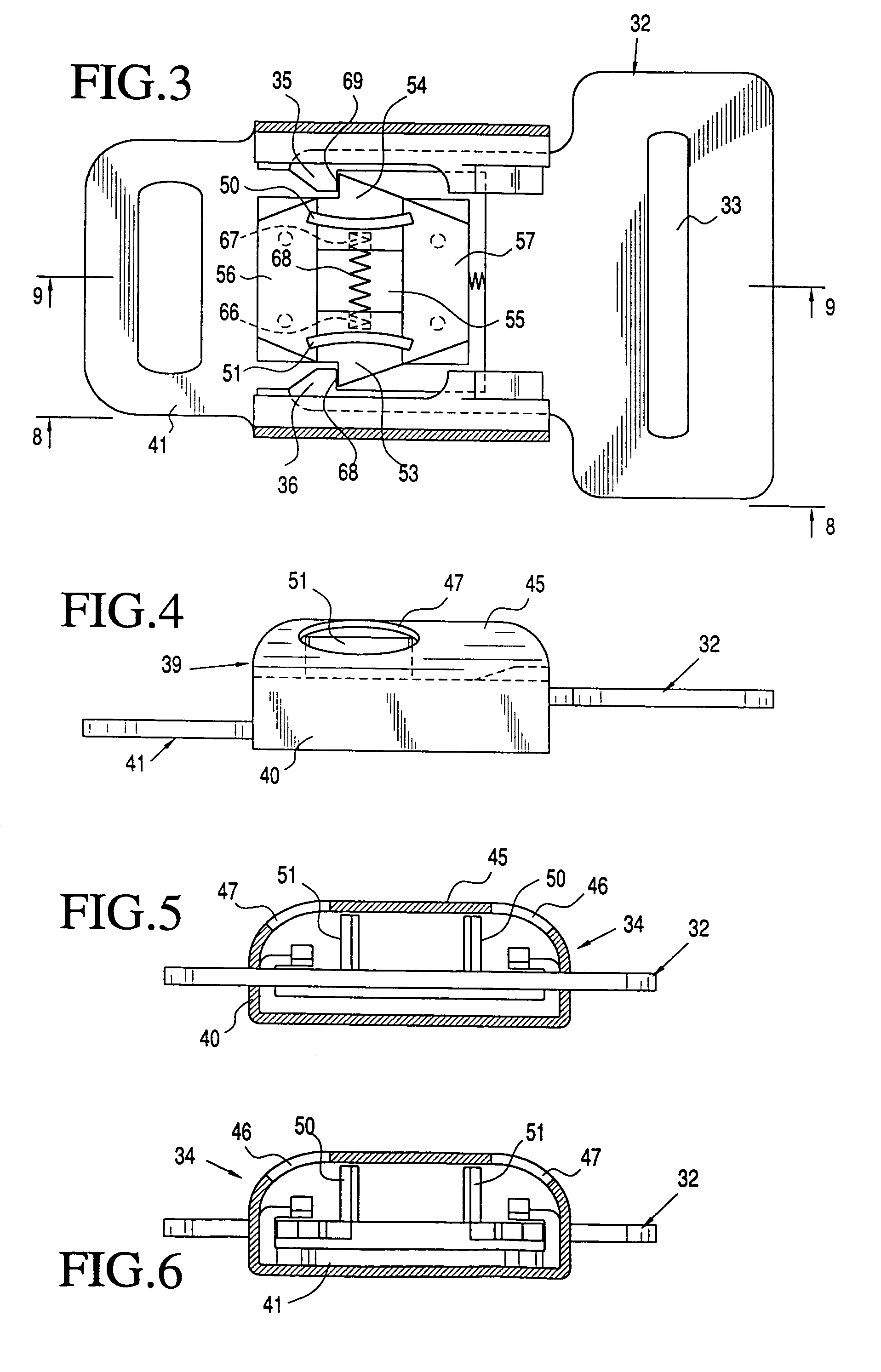
[0069]With continued reference to FIGS. 1–13 of the drawings figures, the first embodiment of non-inertial release restraint buckle of the present invention is shown as used with a seat belt restraint system in an automotive vehicle. The restraint system includes a seat belt 30 in the form of a harness and lap belt that is mounted to a latch plate 32 that is specifically designed to be cooperatively used with a buckle 34. The latch plate 32 includes a body portion having an open slot 33 therein through which the belt extends and also includes a pair of forwardly extending locking tongs 35 and 36 which are spaced from one another. Each locking tong includes a hooked portion 37 and 38, respectively, for purposes of cooperating with locking elements of the buckle 34. As shown, the end portion of each of the tongs 35 and 36 is tapered for purposes which will be described in greater detail hereinafter.

[0070]The buckle 34 includes an outer housing 40 which substantially covers a metallic ...


PUM


Abstract

Body restraint systems for vehicles that include buckles for latching and retaining latch plates associated with safety belts. The buckle of each system includes a pair of oppositely biased latching mechanisms that are operative in such a manner that a force applied to release one latching mechanism from a latch plate inserted within the buckle creates an opposite and equal force against the opposite latching mechanism to thereby positively retain the latch plate within the buckle in a locked position. Release of a latch plate can only occur upon the simultaneous movement of both of the oppositely biased latching mechanisms toward one another by application of manual force and thus release of the latch plate cannot occur by inertial forces that may be encountered in a vehicular accident.

Description

CROSS REFERENCE TO RELATED APPLICATION[0001]This application is a continuation-in-part application of application Ser. No. 10 / 462,738 filed Jun. 17, 2003 now abandoned entitled NON-INERTIAL SAFETY RESTRAINT BELT BUCKLE SYSTEMS in the name of the same inventor.BACKGROUND OF THE INVENTION[0002]1. Field of the Invention[0003]This invention is generally directed to vehicle safety restraint systems including shoulder and lap seat belts and more particularly to such restraint systems that include a buckle that houses oppositely biased locking or latching mechanisms that are operable to resiliently engage locking tongs of a latch plate as a latch plate is inserted within the buckle. The latching mechanisms prevent release of the latch plate due to inertial forces created during a vehicle accident, such as a vehicle roll-over. The latch plate can only be released by manual operating one or more release buttons which cause the simultaneous movement of the latching mechanism in opposite direc...

Claims


Application Information

Patent Timeline
Patent Type & Authority Patents(United States)
IPC IPC(8): A44B21/00A44B11/26A44B99/00A44B11/25
CPCA44B11/2519A44B11/2523Y10T24/45623Y10T24/45654Y10T24/45749Y10T24/45634
Inventor BENEDICT, CHARLES E.
Owner BENEDICT CHARLES E
Why Eureka
Try Eureka