AI technical title is built by Patsnap AI team. It summarizes the technical point description of the patent document.
a technology of a comminution device and a cup is applied in the field of comminution devices, which can solve the problems of high cost of individual parts replacement, high susceptibility to jamming, and large devices, and achieve the effect of minimizing friction and avoiding the damage of cups
Inactive Publication Date: 2006-12-12
MANSEN JOEL D
View PDF2 Cites 13 Cited by
Summary
Abstract
Description
Claims
Application Information
AI Technical Summary
This helps you quickly interpret patents by identifying the three key elements:
Problems solved by technology
Method used
Benefits of technology
Benefits of technology
[0009]In yet another embodiment, the pins are removably fixed to their respective bases, thus allowing pins of various shapes and sizes to be easily inter-changed.
[0027]The invention also provides for a gasket which alleviates the problem of damage to the cups due to different rotational movements. The problem is reduced by the introduction of a tough, low-friction material between the rubbing surfaces. Such a material could, for example, be TEFLON® applied to one or both of the rubbing surfaces.
[0028]The surfaces are smooth and rotation with gentle axial pressure causes effective grinding of materials placed in the male cup. However, due to irregularities in different people's rotational movements (i.e. unnecessary pressure applied, pieces not axially aligned) a gasket / washer of low friction (i.e. Teflon®, PVC) is designed to complement the comminuting device / grinder. Thus the gasket will provide a practical solution for the irregularities of manual implementation. These irregularities can cause damage to the shoulder surface of the male cup and the matching surface of the female cup (the rubbing surfaces).
[0029]To prevent such change, an annulus (washer) of low-friction material may be placed on the male cup to seat against the shoulder surface. Preferably, the washer should fit snugly against the neck adjacent to the shoulder to resist the tendency for it to be separated from the shoulder. The washer may have a flange at a 90 degree angle to the annular portion of the washer to protect the inner surface of the female and outer surface of the male cups and to minimize the friction between them.
Problems solved by technology
One problem with such attempts is their susceptibility to jamming.
Another problem with such devices is the presence of numerous mechanical parts, each of which are susceptible to wear and tear and replacement of the individual parts can be expensive.
Some of these devices are also large and thus not easily portable.
Method used
Image
Click on the blue label to locate the original text in one second.
Reading with bidirectional positioning of images and text.
Examples
example 1
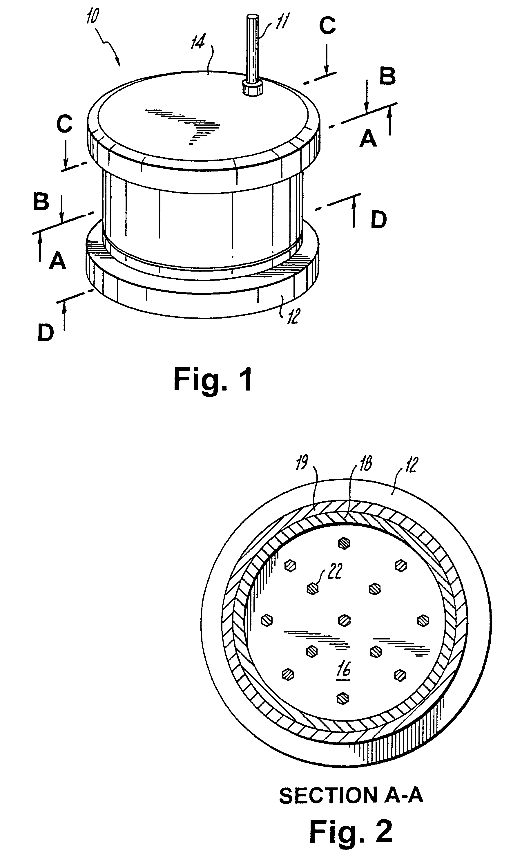
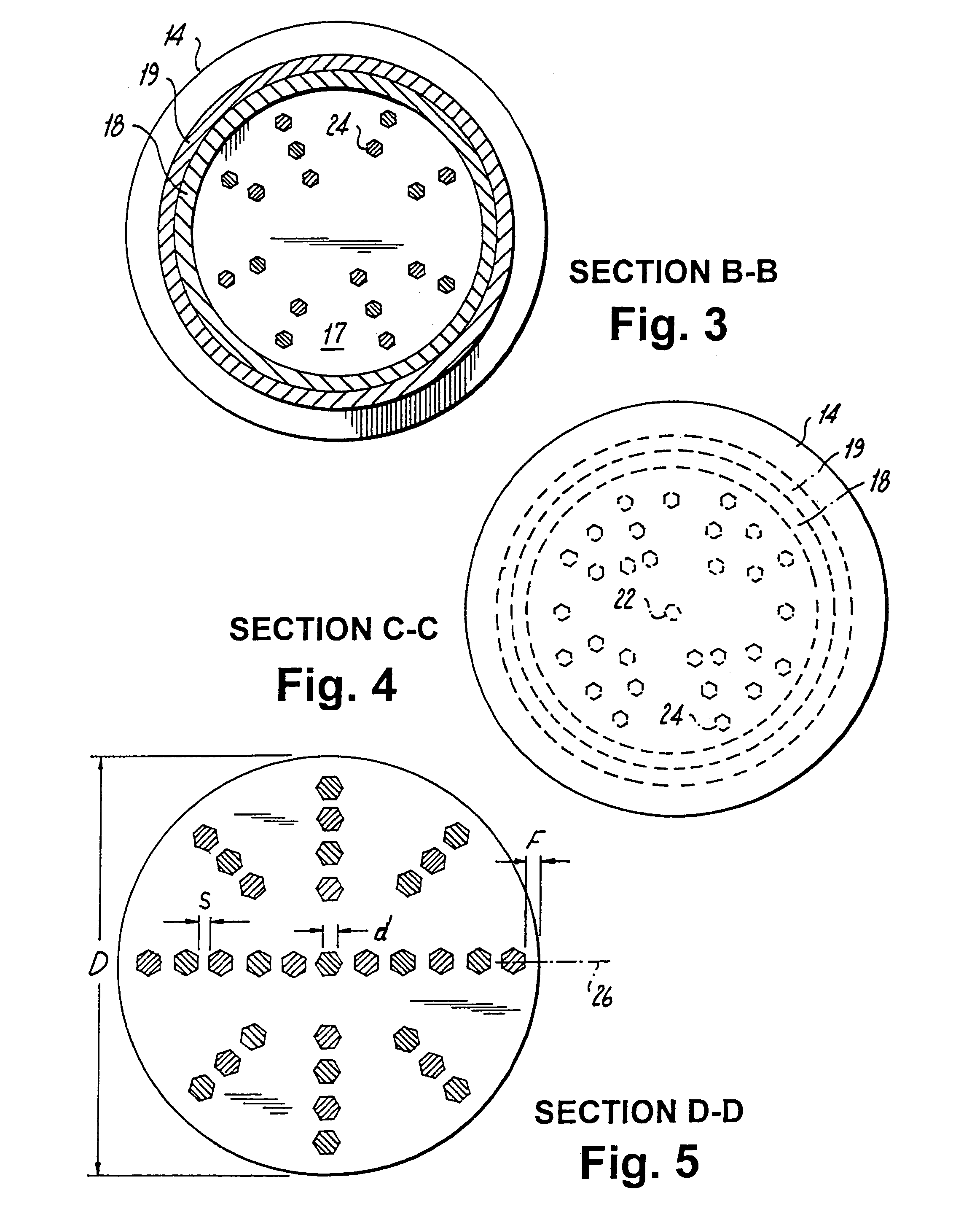
[0071]Any size of the comminuting device and the configuration of the pins 22 in the male mating device 12 can be easily determined by using the formulas described above. Thus, if a male mating section 12 whose internal diameter, D, is 35 mm, F is 0.75 mm, and each pin 22 has a diameter, d, of 1.4 mm with a desired spacing, S, between the interdigitating pins of the assembled device of 1.6 mm, then the total integral odd number of pins required for the assembled device along the major axis of the device would be:
35=(n)(1.4)+1.6(n−1)+2(0.75)
35=1.4n+1.6n−1.6+1.5
35=3.0n−0.1
3.0n=35+0.1
3.0n=35.1
[0072]Since n should be an odd integer, the value of n is rounded off to the nearest odd integer. In this instance n should be 11. In the event that the value of n is an even number, the value of n is rounded off to the nearest odd integer. Thus, if the value of n for a different set of parameters works out to be 12.2, then n should be rounded off to the nearest odd integer. Such number could be e...
example 2
[0079]If it is desired to determine the internal diameter of a male mating section 12 of a comminuting device described herein, knowing that the number, n, of pins to be used is 15, and the diameter, d, of each pin is 1.38 mm, with the spacing, S, between interdigitating pins is 1.62 mm, and F is 0.75 mm, then the internal diameter, D, of the male mating section 12 can be calculated as follows:
D=(n)(d)+S(n−1)+2F
D=(15)(1.38)+1.62(15−1)+2(0.75)
D=20.7+22.68+1.5
D=44.88 mm
[0080]The number of orbits, O, concentric with the central pin is:
O=(n−1) / 2
O=(15−1) / 2
O=14 / 2
PUM
Abstract
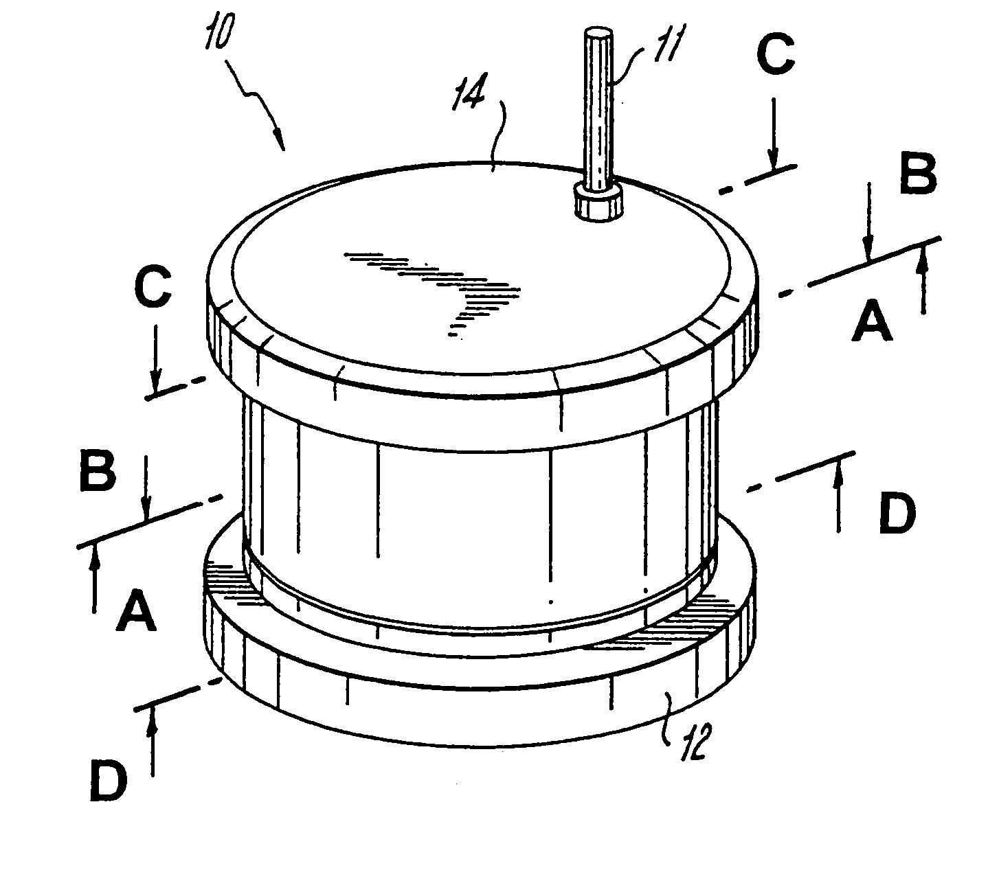
A device for comminuting material comprising first and second mating sections. The mating sections when mated form an enclosed interior chamber with the first and second sections capable of movement relative to each other. The first mating section has a first set of a plurality of pins, which extend from a base of the first mating section and into the interior of the chamber. Similarly, the second mating section has a second set of a plurality of pins extending from a base of the second mating section and into the interior of the chamber. The pins from the first mating section interdigitate with the second set of a plurality of pins when the first and second mating sections are mated, wherein movement of the first and second mating sections relative to one another causes comminution of the material when placed in the chamber. The pins have varying cross-sectional shapes including circular, triangular, and hexagonal.
Description
[0001]This application is a continuation of U.S. patent application Ser. No. 10 / 121,528, filed Apr. 12, 2002, now U.S. Pat. No. 6,834,817, which is a continuation-in-part of U.S. patent application Ser. No. 09 / 891,807, filed Jun. 26, 2001, now U.S. Pat. No. 6,517,018, which is based on U.S. Provisional Patent Application No. 60 / 313,396, filed Aug. 17, 2001.BACKGROUND OF THE INVENTION[0002]1. Field of the Invention[0003]This invention relates to the comminution of raw materials[0004]2. Prior Art[0005]Numerous attempts have been made for comminuting raw material into a desired particulate size. One problem with such attempts is their susceptibility to jamming. Another problem with such devices is the presence of numerous mechanical parts, each of which are susceptible to wear and tear and replacement of the individual parts can be expensive. Some of these devices are also large and thus not easily portable.SUMMARY OF THE INVENTION[0006]The comminuting device or, for brevity herein, th...
Claims
Application Information
Patent Timeline
Application Date:The date an application was filed.
Publication Date:The date a patent or application was officially published.
First Publication Date:The earliest publication date of a patent with the same application number.
Issue Date:Publication date of the patent grant document.
PCT Entry Date:The Entry date of PCT National Phase.
Estimated Expiry Date:The statutory expiry date of a patent right according to the Patent Law, and it is the longest term of protection that the patent right can achieve without the termination of the patent right due to other reasons(Term extension factor has been taken into account ).
Invalid Date:Actual expiry date is based on effective date or publication date of legal transaction data of invalid patent.

