
Surface acoustic wave device having improved performance and method of making the device

a surface acoustic wave and device technology, applied in the direction of piezoelectric/electrostrictive device material selection, device material selection, generator/motor, etc., can solve the problems of voids, current saw devices may develop issues concerning hillocks, problems that are easy to occur for a saw device, and saw devices may experience deviation or shift away from desired frequency performan

Inactive Publication Date: 2006-12-12
OC OERLLIKON BALZERS AG
View PDF34 Cites 20 Cited by
  • Summary
  • Abstract
  • Description
  • Claims
  • Application Information

AI Technical Summary

Benefits of technology

This patent describes a special type of electronic component called a surface acoustic wave (SAW) that can be used in various applications such as communication devices or sensors. One important feature of this SAW is its ability to have multiple layers made up of different materials. These layers help improve performance by adding new functions like reducing interference or improving signal quality. In particular, there are several layers made of metal which provide strength and durability to the overall structure. Another key element is the use of a specific material that helps make the metal layer harder without compromising its function. Overall, these technical improvements enhance the reliability and efficiency of SAW components.

Problems solved by technology

The technical problem addressed in this patent text is the potential for performance issues in surface acoustic wave (SAW) devices caused by metal migration and hillocks, and the need for improved power durability in SAW antenna duplexers. Previous attempts to improve power durability have involved adding small amounts of dopant to aluminum metal, but this can lead to increased electrical resistance. The patent seeks to address these issues and provide a solution for improving the durability of SAW devices.

Method used


Image

  • Surface acoustic wave device having improved performance and method of making the device
  • Surface acoustic wave device having improved performance and method of making the device
  • Surface acoustic wave device having improved performance and method of making the device

Examples


Embodiment Construction

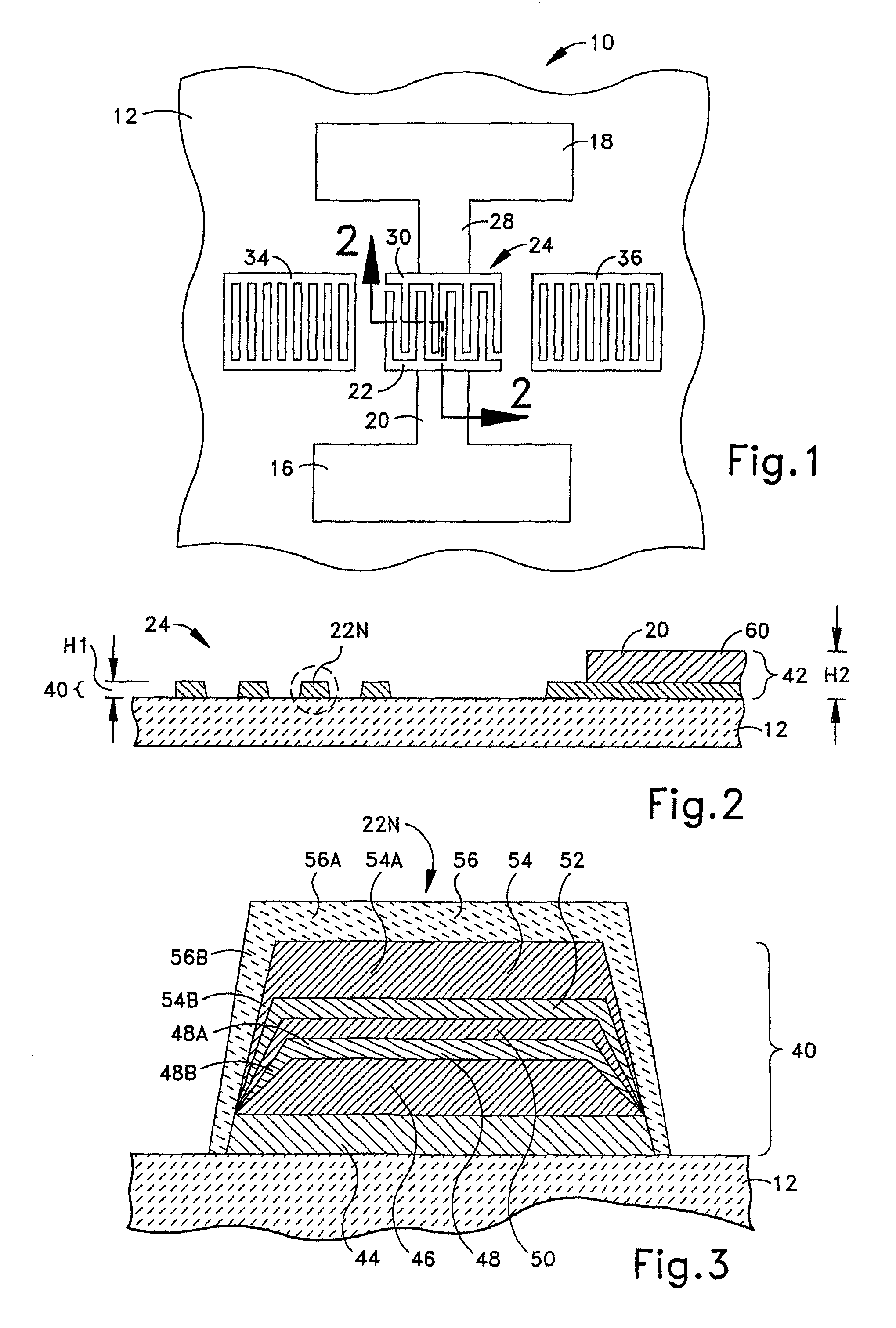
[0021]One example of a surface acoustic wave (SAW) device 10 in accordance with the present invention is schematically shown in FIG. 1. The SAW device 10 is provided on a substrate 12. The substrate 12 is planar with a flat upper (as viewed in the Figures) surface. The substrate 12 may be of any suitable material such as quartz, lithium niobate, or lithium tantalate.

[0022]The SAW device 10 is usable in any application such as a filter. In one specific application, the SAW device is utilized as an antenna duplexer for use in a communication device such as a cellular telephone handset. Within the example device of a telephone handset, the SAW device is relatively small due in part to the compact nature of handsets.

[0023]In view of the relatively small size, the SAW device 10 includes two electrically conductive bond pads 16 and 18 for electrical connection of the SAW device to circuitry external to the SAW device. Extending from the first bond pad 16 is an electrically conductive busb...


PUM


Abstract

A surface acoustic wave device includes a transducer electrode formed on a substrate. In one aspect, the electrode has a plurality of layers. At least one of the layers is metal and another of the layers is a material for providing a hardening effect to the metal layer by reinforcement with Al2O3 precipitates. In another aspect, the electrode is electrically connected to a metal component that permits electrical connection of the surface acoustic wave device to an electrical device external to the surface acoustic wave device. The electrode has a metal portion of a first metallization. The component is of a second, different metallization. In other aspects, the surface acoustic wave device is made via a method to have such structural aspects.

Description


Claims


Application Information

Patent Timeline
Owner OC OERLLIKON BALZERS AG
Learn More