Manipulator for positioning a test head

a technology of manipulator and test head, which is applied in the field of manipulators, can solve the problems of unsatisfactory rotary guide of the known manipulator for installing and removing the test head, and the difficulty of pulling the connecting cable through the opening in the supporting plate, and achieves the effect of durable and reliable mounting

Inactive Publication Date: 2006-12-19
HEIGL HELMUTH
View PDF9 Cites 0 Cited by
  • Summary
  • Abstract
  • Description
  • Claims
  • Application Information

AI Technical Summary

Benefits of technology

[0010]The manipulator in accordance with the invention is based on having discovered that to facilitate securing a test head, both the supporting plate supporting the test head and the mounting plate secured to the positioning means each comprises at least one feeder sector now making it possible to insert the connecting cable into the concentric openings of mounting plate and supporting plate sideways. Unlike prior art this now eliminates having to pull the connecting cable through the opening in the supporting plate. To insert the connecting cable the feeder sectors are positioned concentrically. Once the connecting cable is located in the concentric openings it is expedient to turn the supporting plate relative to the mounting plate, resulting in the feeder sectors no longer being concentrical so that the connecting cable is effectively prevented from dropping out of the openings. In addition, it has been discovered that in the incongruent positions of the feeder sectors the strength of the rotary guide is enhanced to thus take into account the relatively heavy weight of a test head.
[0021]Preferably, the traction means acting by friction or positive contact is secured to the ends of the mounting ring with the advantage that the aperture of the mounting ring and thus the feeder sectors of the mounting plate and supporting plate remain free. Although securing the traction means to the ends of the mounting ring results in the test head not being rotatable through 360°, but merely by a pivot angle primarily depending on the size of the aperture of the mounting ring, such a positioning means has proven in practice to be sufficient for precisely positioning the test head at the handler, it having been discovered in this case to advantageously guide the traction means via guide pulleys to ensure an adequate angle of wrap.

Problems solved by technology

Even though being able to open up the mounting ring facilitates clamping in place the supporting plate, the rotary guide of the known manipulator has proven to be unsatisfactory for installing and removing the test head.
Pulling the connecting cable through the opening in the supporting plate is additionally made more difficult because the connecting cable, as a rule, is relatively thick and comparatively inflexible.

Method used


Image

  • Manipulator for positioning a test head
  • Manipulator for positioning a test head
  • Manipulator for positioning a test head

Examples


Embodiment Construction

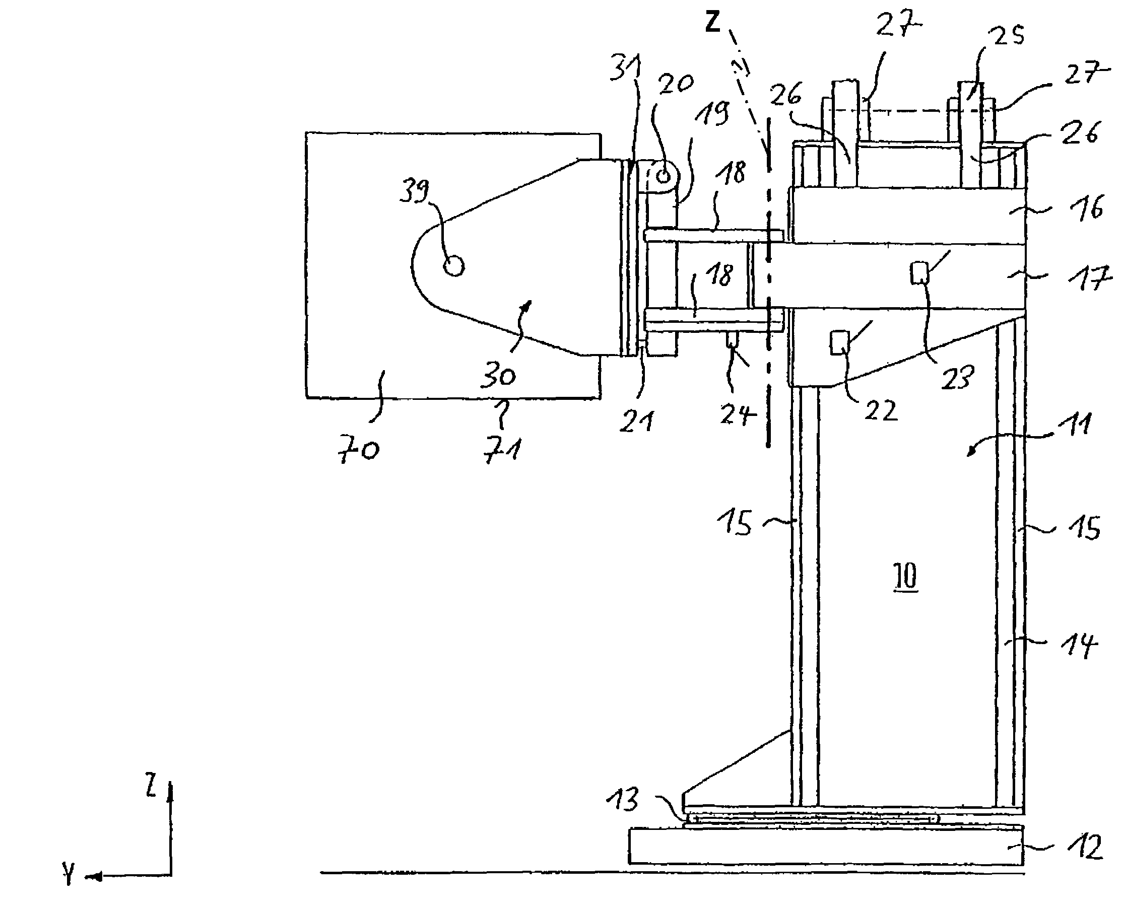
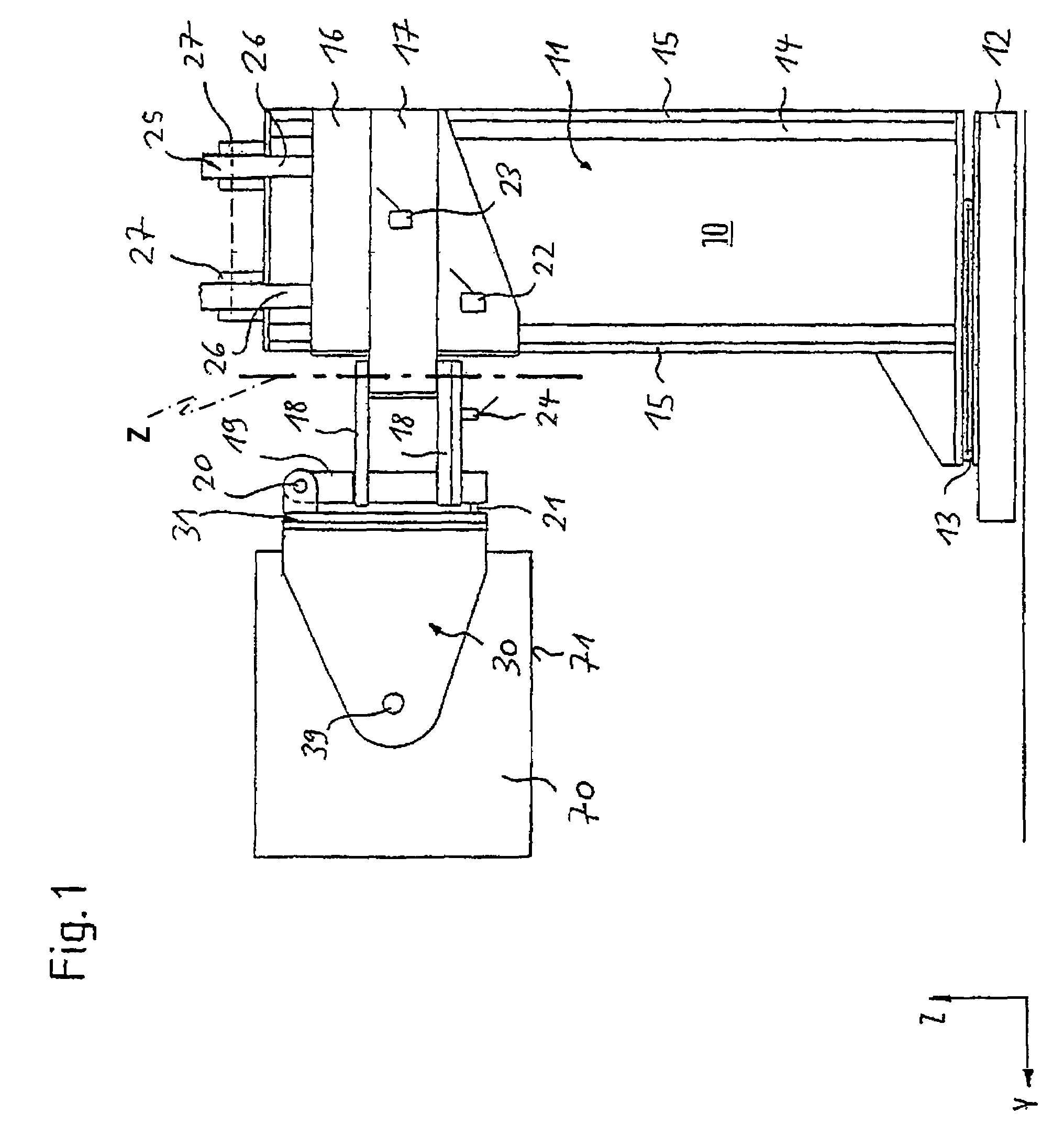
[0031]Referring now to FIG. 1 there is illustrated a manipulator serving to position a test head 70 on a device handler (not shown) such as, for example, an IC handler or wafer prober. For this purpose, the manipulator comprises positioning means 10 having a column 11 extending in the direction of a vertical axis z. The column 11 is composed of two uprights 14 spaced away from each other and arranged on a rotatable platform 13. The rotatable platform 13 located on a bed 12 permits rotation of the column 11 about the vertical axis z. Where necessary, the rotatable platform 13 may be guided on rails to permit horizontal displacement of the column 11.

[0032]Mounted on the uprights 14 are linear guides 15 by means of which a slave member 16 can be moved along the column 11, whereby the slave member 16 can be powered manually, hydraulically, pneumatically and / or electrically. In the latter case the linear guides 15 are expediently components of a linear motor. By means of a locking lever ...


PUM


Abstract

A manipulator, particularly for positioning a test head (70), is provided with positioning means (10) for three-dimensionally positioning the test head (70). In addition, the manipulator is provided with a mount (30) for the test head (70). The mount (30) comprises a rotary guide (31) by means of which the test head (70) is rotatable about an axis of rotation (y). The rotary guide (31) comprises a mounting plate (40) connected to the positioning means (10) and a supporting plate (50) rotatable relative to the mounting plate (40) about the axis of rotation (y), the test head (70) being securable to the supporting plate (50). Mounting plate (40) and supporting plate (50) have concentric openings (41, 51) for receiving a connecting cable connecting the test head (70) and feeder sectors (42, 52) forming an aperture open to the edge of each of the mounting plate (40) and supporting plate (50).

Description

BACKGROUND OF THE INVENTION[0001]1. Field of the Invention[0002]The invention relates to a manipulator serving particularly to position a test head. The manipulator comprises positioning means for three-dimensionally positioning a test head. In addition, the manipulator is provided with a mount for the test head. The mount comprises a rotary guide by means of which the test head is rotatable about an axis of rotation. The rotary guide comprises a mounting plate connected to the positioning means and a supporting plate rotatable relative to the mounting plate about the axis of rotation, the test head being securable to the supporting plate. Mounting plate and supporting plate have concentric openings for receiving a connecting cable connecting the test head.[0003]2. Background Art[0004]Such a manipulator usually has several degrees of translatory and rotational motion in being suitable for precisely three-dimensionally positioning a test head as required as a rule in the testing of e...

Claims


Application Information

Patent Timeline
Patent Type & Authority Patents(United States)
IPC IPC(8): G01D21/00F16M11/06F16M11/12G01R31/28
CPCF16M11/06F16M11/10F16M11/12F16M11/2014G01R31/2887F16M2200/04
Inventor HEIGL, HELMUTH
Owner HEIGL HELMUTH
Why Eureka
Try Eureka