Braking mechanism for nail driver

a braking mechanism and nail driver technology, applied in the direction of nailing tools, stapling tools, manufacturing tools, etc., can solve the problems of failure of the braking mechanism, leaf springs that may not provide enough resilient force, and are not easy to prevent, so as to achieve reliable braking mechanisms

Inactive Publication Date: 2006-12-19
DE POAN PNEUMATIC
View PDF10 Cites 22 Cited by
  • Summary
  • Abstract
  • Description
  • Claims
  • Application Information

AI Technical Summary

Benefits of technology

[0006]The present invention is to provide a reliable braking mechanism for a nail driver so that a securing slide r

Problems solved by technology

However, the conventional stopper cannot provide secure restrain so that the securing slide rod is easily released to cause failure of the braking mechanism.
However, the leaf spring may fail to provide enough resilient force because of the structure

Method used


Image

  • Braking mechanism for nail driver
  • Braking mechanism for nail driver
  • Braking mechanism for nail driver

Examples


Embodiment Construction

[0015]In order that those skilled in the art can further understand the present invention, a description will be described in the following in details. However, these descriptions and the appended drawings are only used to cause those skilled in the art to understand the objects, features, and characteristics of the present invention, but not to be used to confine the scope and spirit of the present invention defined in the appended claims.

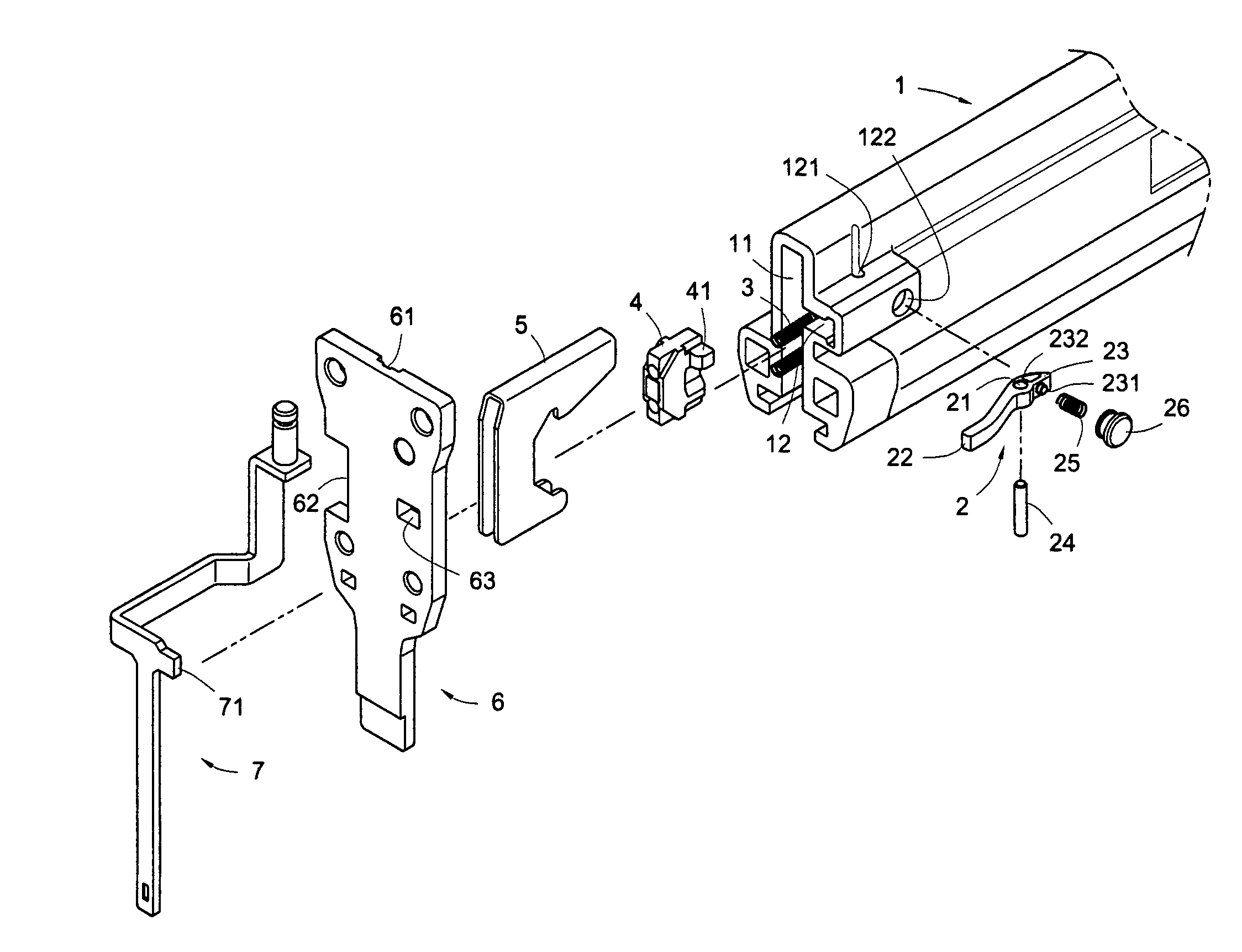
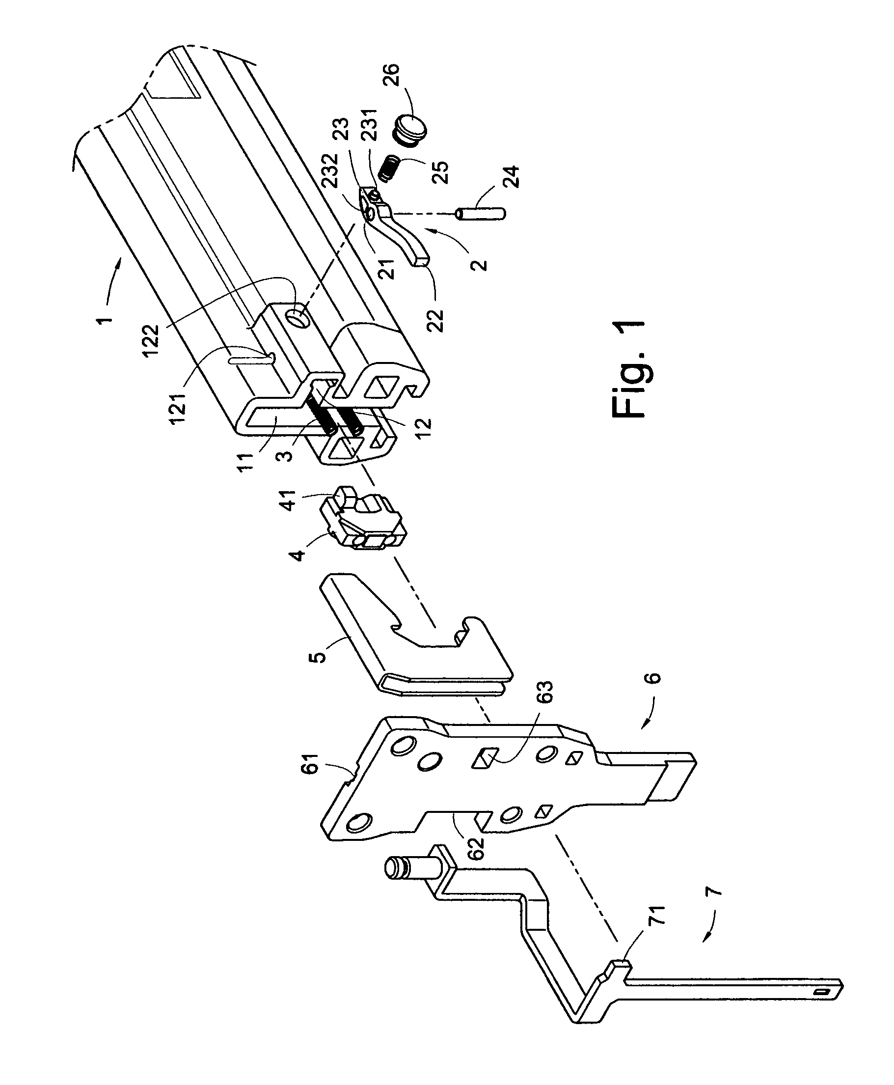
[0016]Referring to FIG. 1, a nail driver of the present invention includes a guiding plate 6, a securing slide rod 7, a nail cartridge 1 and a braking unit 2.

[0017]The guiding plate 6 includes a punch channel 61 formed on one surface, a guiding portion 62 formed on one side and an opening 63 formed thereon.

[0018]The securing slide rod 7 with the lower body attached to the other surface of the guiding plate 6 can slidably move within the guiding portion 62, so that a lower striking end of the securing slide rod 7 can move downward to press against ...


PUM

PropertyMeasurementUnit
Resilienceaaaaaaaaaa

Abstract

A nail driver includes a cell formed inside a nail cartridge. A braking unit with one end formed as a retaining portion and the other end formed as a contact portion is pivotally installed in the cell. A resilient member is installed in the cell for pressing on the contact portion to swing the retaining portion to a releasing position so that a securing slide rod can freely slide to have the nail drive being actuated when there is any nail in the nail cartridge. When there is no more nail, a nail pusher pushed by a spring makes a protrusion of the nail pusher pressing on the contact portion against the resilient member to swing the retaining portion to a restraining position to block in the moving path of an extending portion of the securing slide so that the nail drive cannot be actuated until the nails are reloaded.

Description

BACKGROUND OF THE INVENTION[0001]The present invention relates to a braking mechanism for a nail driver, more particularly to a braking mechanism to restrain the movement of a securing slide rod when a nail driver runs out of nails.[0002]A braking mechanism for a nail driver is to invalidate the trigger of the nail driver when the nail cartridge is empty, so that the user is reminded of reloading the nails.[0003]Conventionally, a braking mechanism for the nail driver includes a nail pusher formed with a protrusion to press a stopper installed on a nail cartridge so that the stopper can restrain the movement of the securing slide rod when no more nail exists in the nail cartridge.[0004]However, the conventional stopper cannot provide secure restrain so that the securing slide rod is easily released to cause failure of the braking mechanism. Moreover, after the nails are reloaded in the cartridge, the conventional braking mechanism utilizes a leaf spring to push back the stopper. Howe...

Claims


Application Information

Patent Timeline
IPC IPC(8): B25C1/04
CPCB25C1/008
Inventor WEN, WAN-FU
Owner DE POAN PNEUMATIC
Why Eureka
Try Eureka