
Track type transportation system

Active Publication Date: 2010-02-11
MITSUBISHI HEAVY IND ENG LTD
View PDF8 Cites 7 Cited by
  • Summary
  • Abstract
  • Description
  • Claims
  • Application Information

AI Technical Summary

Benefits of technology

[0028]The present invention is devised in view of the above-mentioned problems inherent to the above-mentioned conventional technology, and accordingly, an object of the present invention is to provide a detection mechanism which is capable of precisely detecting a deviated value of a vehicle widthwise of a track and which is highly reliable, in a track type transportation system incorporating an automatic steering mechanism and a fail-safe mechanism as stated above.
[0029]Further, as to another object of the present invention, in addition to a noncontact type displacement meter, there is also provided a contact type displacement meter which is adapted to make contact with a protection track only when the noncontact type displacement meter is malfunctioning, thereby it is possible to provide a highly reliable detection mechanism.

Problems solved by technology

Further, a noncontact type measuring instrument which has a high degree of measuring accuracy, and which does not cause any wearing problem is preferably used as a measuring device therefor, and such a noncontact type measuring instrument would cause a risk with respect to its environmental resistance in view of rain water, sunlight or the like.
Thus, there would be possibly caused a trouble throughout the entire system upon occurrence of a detection error.

Method used


Image

  • Track type transportation system
  • Track type transportation system
  • Track type transportation system

Examples


embodiment 1

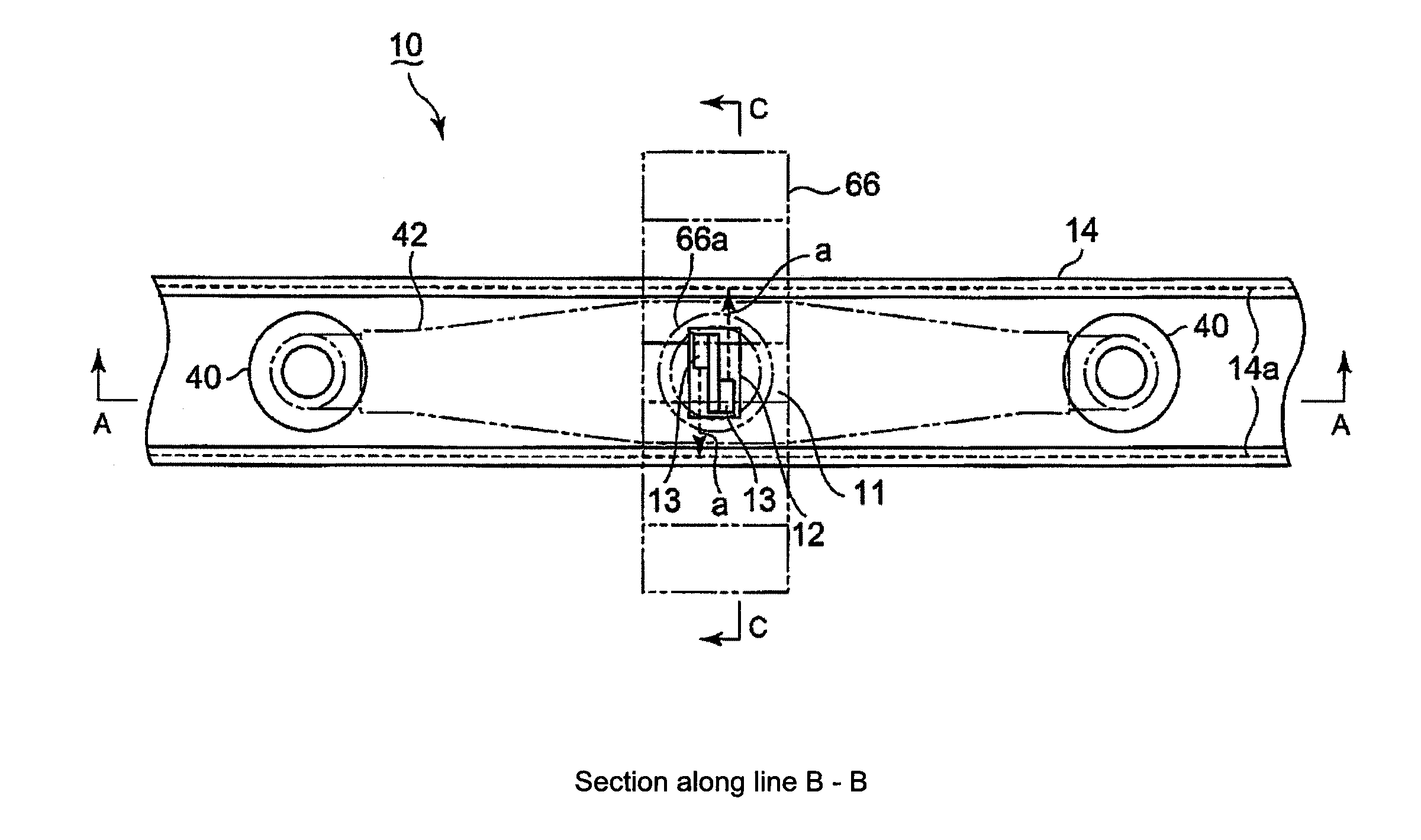
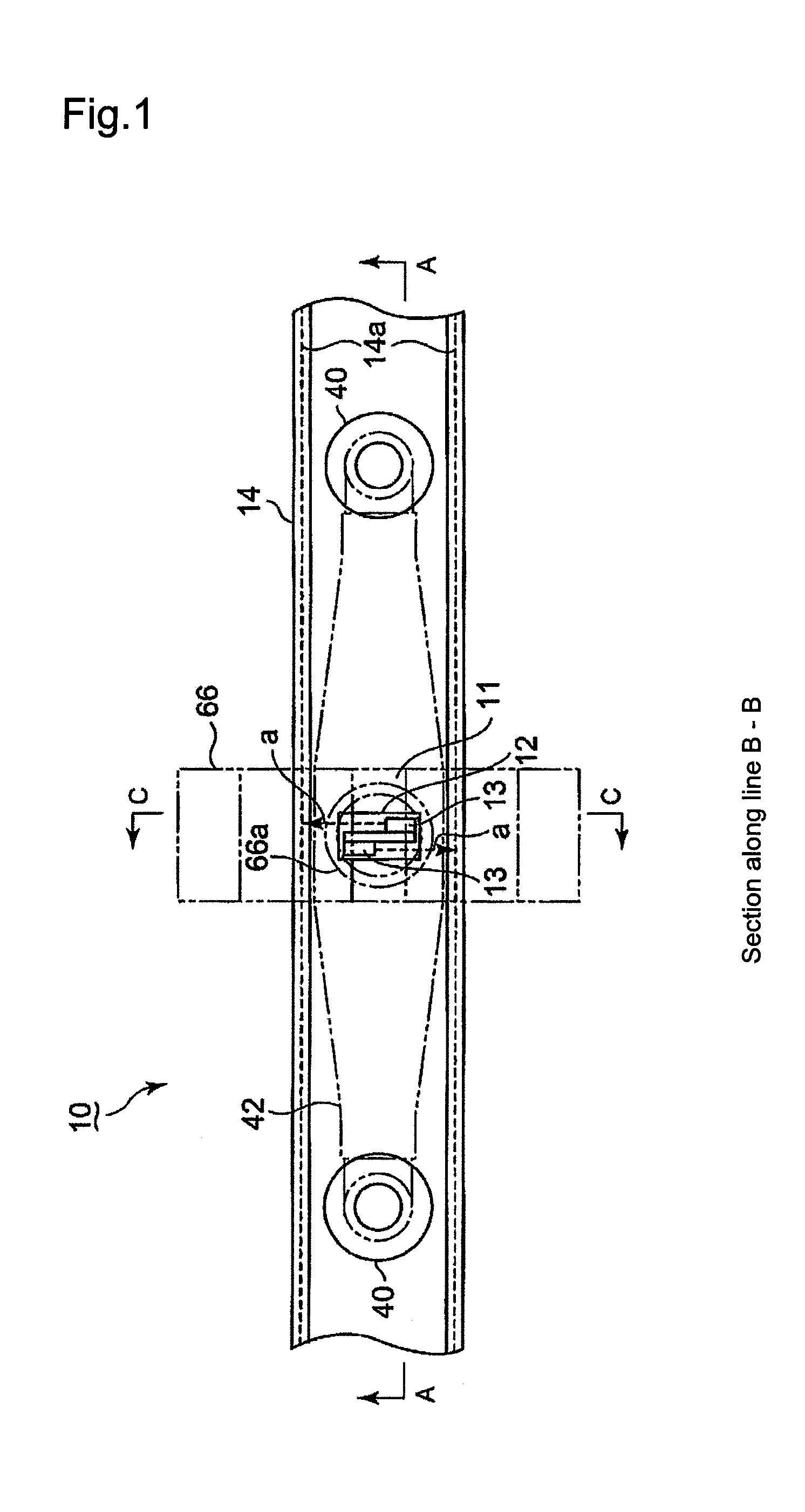
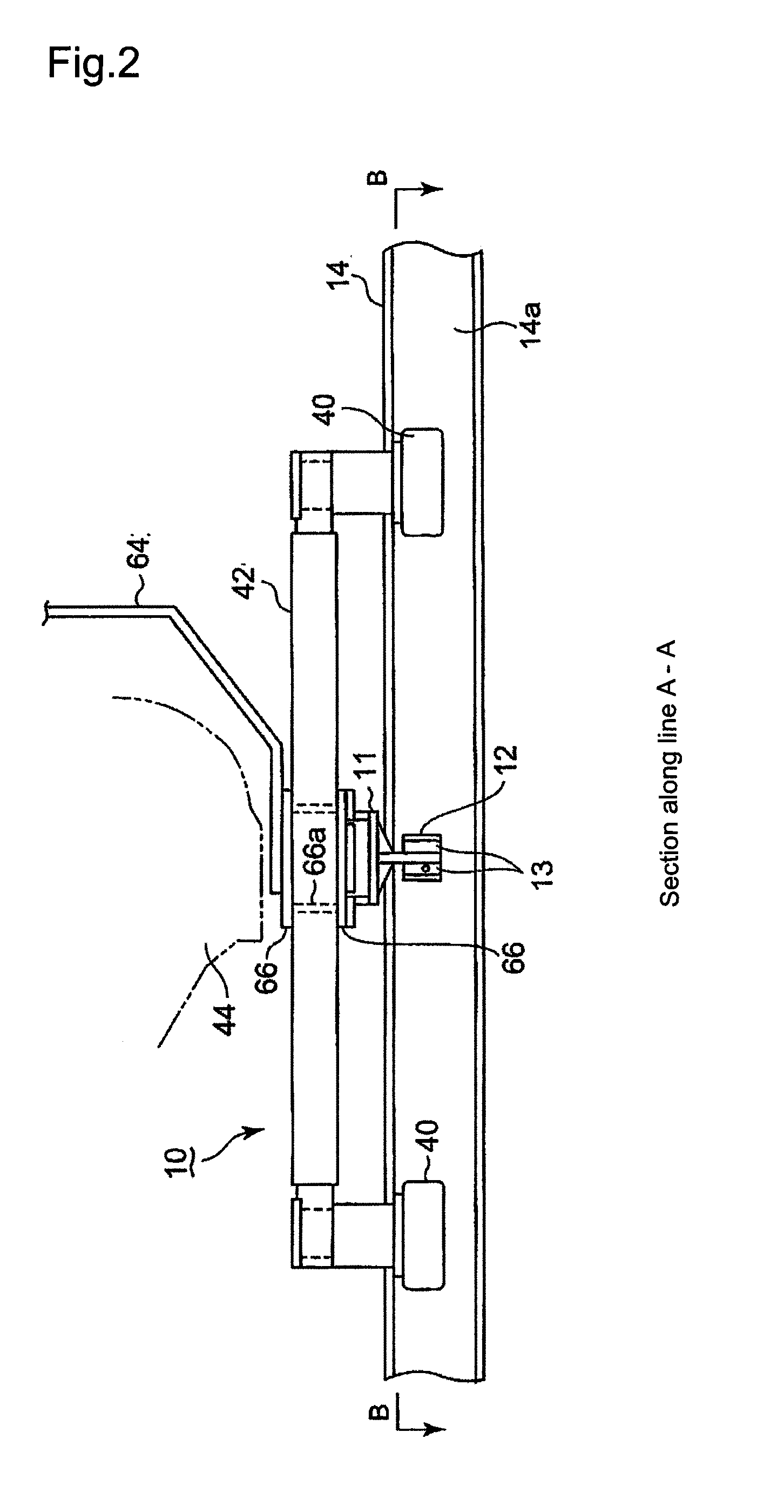
[0091]Explanation will be made of a first embodiment of a track type transportation system in the present invention with reference to FIGS. 1 to 3 in which FIG. 1 is a sectional plan view (along line B-B in FIG. 2) illustrating a fail-safe mechanism in this embodiment, FIG. 2 is a sectional elevation view (along line A-A in FIG. 1) and FIG. 3 is a sectional side view (along line C-C in FIG. 1).

[0092]The configurations of an automatic steering mechanism and the fail-safe mechanism 10 in this embodiment are the same as those explained in the above-mentioned Patent Document 1, and accordingly, explanation thereto will be omitted. In this embodiment, there is provided displacement meters for detecting a deviated value of the pivotal center of a protection arm with respect to a protection track (a deviation value of the pivotal center of the protection arm 42 widthwise of the protection track 42) in combination of the automatic steering mechanism and the fail-safe mechanism as disclosed ...

embodiment 2

[0104]Next, explanation will be made of a second embodiment of the present invention with reference to FIGS. 6 and 7 in which FIG. 6 is a sectional plan view (along line G-G in FIG. 7) and FIG. 7 is a sectional elevation view (along line F-F in FIG. 6). In this embodiment, in comparison with the first embodiment, a pair of laser type displacement meters 13, 13 are located at the position of the center of the axle and are arranged so that laser beams a therefrom are irradiated onto the side walls 14a of the protection track 14, obliquely thereto with oblique angles. Further, a sensor cover 12 surrounding the laser type displacement meters 13, 13 are also provided.

[0105]With the embodiment stated above, the irradiation distances of the laser beams a from the laser type displacement meters 13, 13 to the left and right side walls 14a can be sufficiently ensured. Thus, the irradiation distances of the laser beams a can afford carrying out precised measurement, thereby it is possible to e...

embodiment 3

[0106]Next, explanation will be made of a third embodiment of the present invention with reference to FIGS. 8 and 9 in which FIG. 8 is a sectional plan view (along line I-I in FIG. 9), and FIG. 9 is a section elevation view (along line H-H in FIG. 8), In this embodiment, a pair of leaser type displacement meters 13, 13 which are provided at the pivotal center of the protection arm by the support bracket 11, are arranged being directed in the running direction b of the protection wheels 42. Further, a reflector frame 16 is set between the displacement meters. The support bracket 11 is secured in its center part with upper and lower fixing plates 21 interposing therebetween the reflector frame 16 which is therefore held between the fixing plates 21 and extended in a horizontal direction.

[0107]The reflector frame 16 is fixed thereto with reflectors 17, and the reflector frame 16 is attached at its upper and lower surface with bolts for fixing the reflector frame 16 to the fixing plates...


PUM


Abstract

In a track type protection system comprising an automatic steering mechanism and a fail-safe mechanism, provided is a detection mechanism which can detect a deviated value of a vehicle, widthwise of a track, and which is highly reliable. The track type transportation system in which the vehicle runs on the road surface of the track, comprising the steering mechanism for automatically steering the front and rear wheels of the vehicle by means of actuators, and the fail-safe mechanism composed of a protection track defined on the road surface of the track, and protection wheels provided in the lower part of the vehicle and adapted to run in the protection track without making contact with the protection track, wherein there are provided a pair of noncontact type displacement meters 13 which are attached to a support bracket 64 suspended downward from the lower part of the vehicle body, and which are arranged in the protection track 14 so as to irradiate detection waves a onto the left and right side walls 14a of the protection track, thereby the distances from the noncontact type displacement meters 13 to the left and right side walls of the protection track are measured by the pair of noncontact type displacement meters.

Description

BACKGROUND OF THE INVENTION[0001]1. Technical Field[0002]The present invention relates to a track type transportation system for a vehicle which runs on a predetermined track, and in particular to a track type transportation system in which the front and rear wheels of a vehicle are automatically steered by actuators, and which incorporates therein a fail-safe mechanism for preventing the vehicle from coming off from a track upon malfunctioning of an automatic steering mechanism.[0003]2. Background Art[0004]The applicant has already proposed a track type transportation system for a vehicle, incorporating a steering mechanism for automatically steering the front and rear wheels of the vehicle by means of actuators so as to allow the vehicle to run on a predetermined track, and a fail-safe mechanism for preventing the vehicle from coming off the track even though the automatic steering mechanism is malfunctioning (refer to Patent Document: Japanese Patent Laid-Open No. 2006-306334). E...

Claims


Application Information

Patent Timeline
IPC IPC(8): G06F17/00
CPCB61B10/04B61F9/005B61F9/00B62D1/265B61B13/00G01S13/08
Inventor MORICHIKA, SHUNJIMORITA, KATSUAKIYAMAGUCHI, MASAHIROHOSHI, MITSUAKIKATAHIRA, KOUSUKE
Owner MITSUBISHI HEAVY IND ENG LTD
Learn More