Wheel guide arrangement for a steered motor vehicle wheel

a technology for steering motor vehicles and wheel guides, which is applied in the direction of steering parts, vehicle components, and resilient suspensions, etc., can solve the problems of requiring relative low steering forces, and achieve low overall height, low steering forces, and small coupling distances

Inactive Publication Date: 2006-12-19
DAIMLER AG
View PDF12 Cites 9 Cited by
  • Summary
  • Abstract
  • Description
  • Claims
  • Application Information

AI Technical Summary

Benefits of technology

[0007]As a result, in a downward projection onto a horizontal plane, the connecting points of the arms to the steering knuckle can be close to one another, so that there is a small coupling distance between the joints. As a result, only relatively low steering forces are required.
[0008]Also, the support arms together with their connections to the steering knuckle, have a low overall heights so that, for example, sufficient ground clearance is ensured. It is likewise possible to use this wheel guide arrangement also for driven steered vehicle wheels, since the type of arm connection provides sufficient free space for a drive shaft leading to the wheels.
[0009]In a refinement of the invention, the connecting points are at different distances from an approximately vertical wheel center plane extending in the direction of travel of a vehicle wheel. Likewise, the connecting point which is closer to the wheel axis may be arranged in the direction of travel in front of the wheel axis. In addition to kinematic benefits during steering or during the upward and downward stroke of the vehicle wheel, these structural arrangements have the advantage that the bearing journals of the ball joints of the two arms can extend essentially in the same direction and, nevertheless, sufficient construction space is available for connecting the bearing journals operatively to the connecting structure. These connections are expediently designed to be releasable, for example in the form of screw connections.

Problems solved by technology

As a result, only relatively low steering forces are required.

Method used


Image

  • Wheel guide arrangement for a steered motor vehicle wheel
  • Wheel guide arrangement for a steered motor vehicle wheel
  • Wheel guide arrangement for a steered motor vehicle wheel

Examples


Embodiment Construction

[0016]In the following description, identical or similar components are indicated by the same reference symbols.

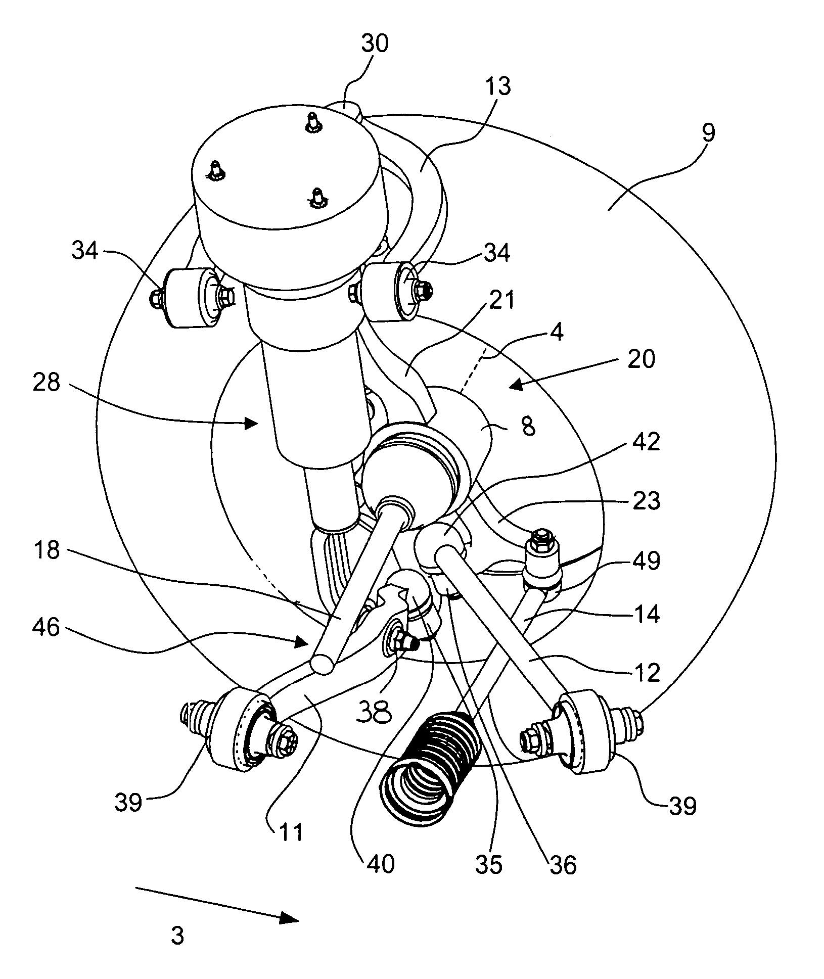
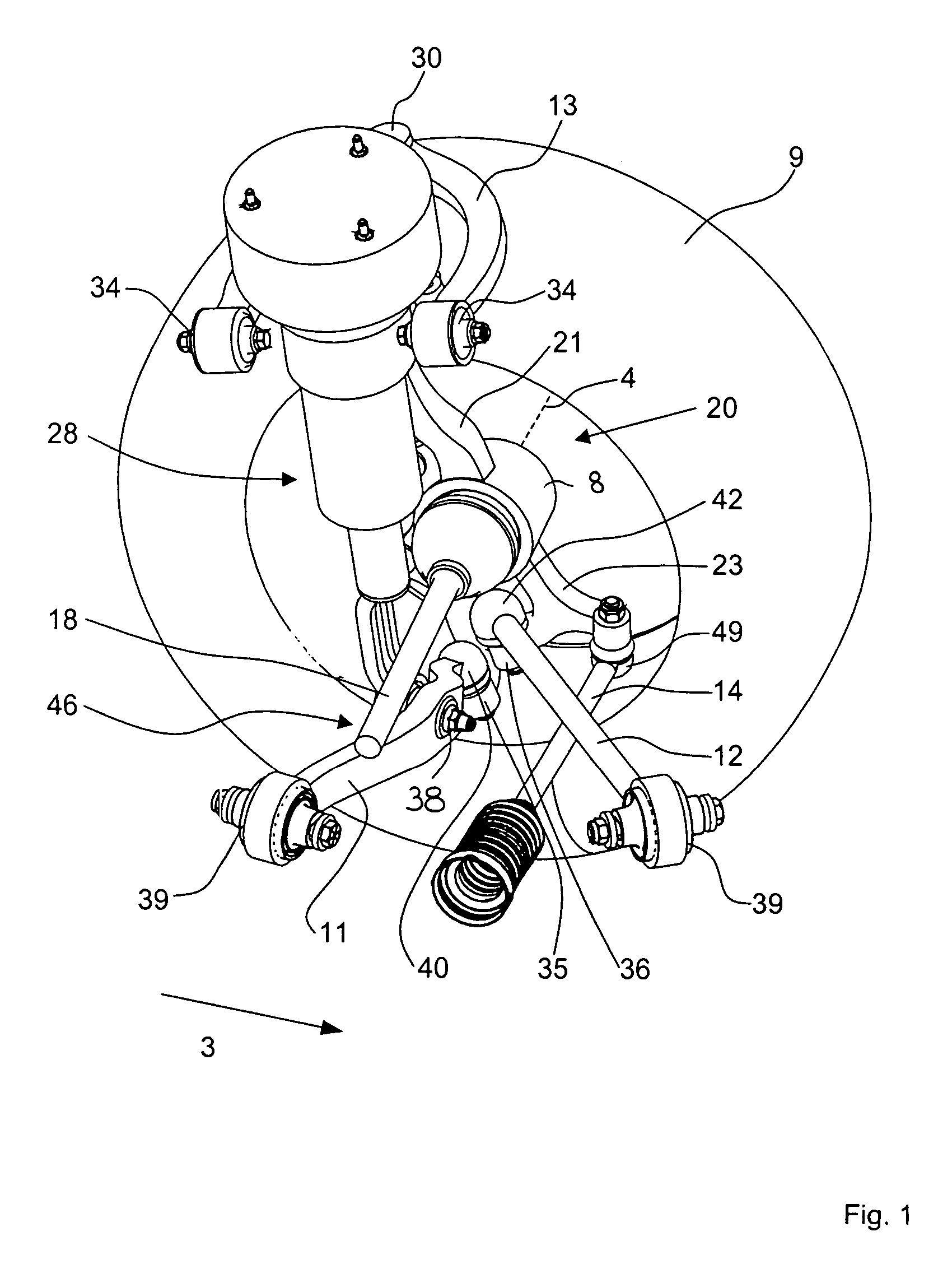
[0017]FIG. 1 is a perspective view of a wheel suspension of a driven steerable left front wheel 9 of a motor vehicle. The vehicle wheel 9 is mounted rotationally movably in a (concealed) reception structure 8 for a wheel mount of steering knuckle 20.

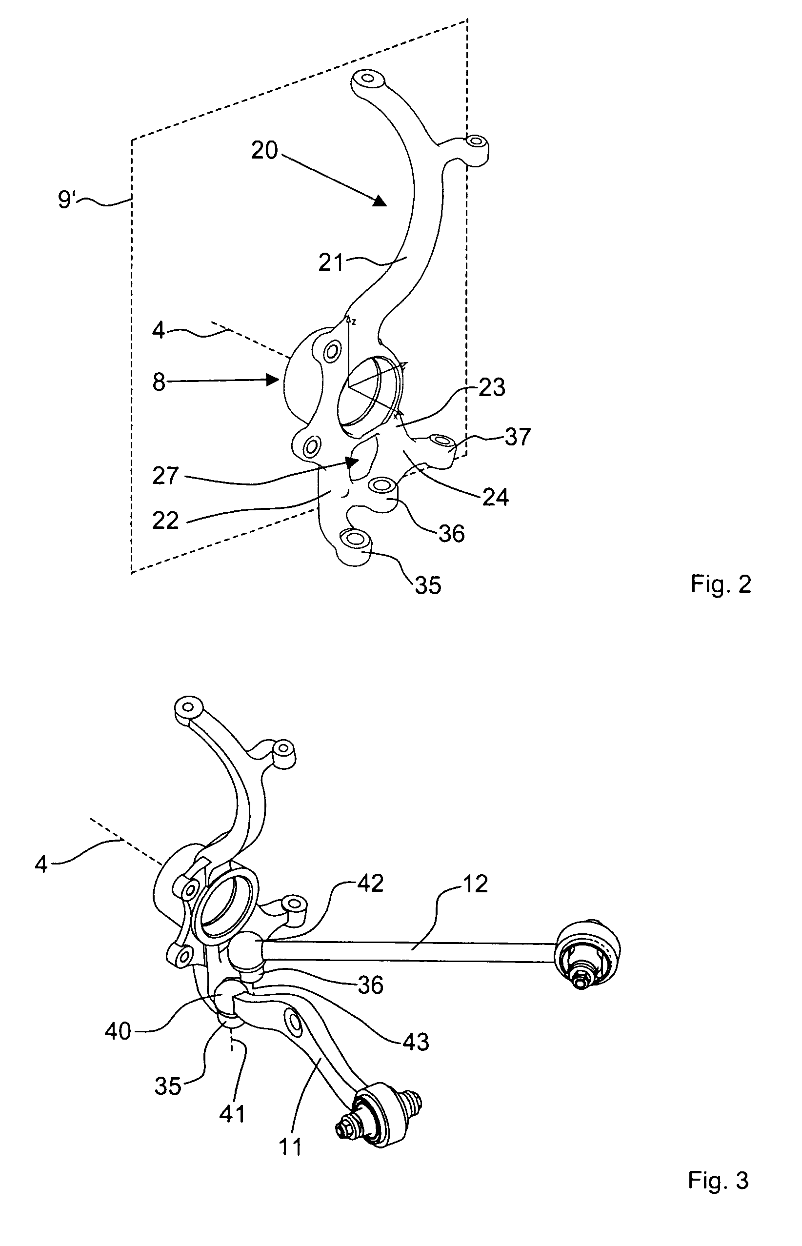
[0018]Above the reception structure 8, the steering knuckle 20 is curved in the form of a goose neck 21. At the upper end of the goose neck 21, the steering knuckle 20 is connected to a wishbone 13 in an articulated manner via an upper ball joint 30. The other two ends of the wishbone 13 are supported pivotably movably on the vehicle body or frame, (not illustrated) of the motor vehicle via bearings 34, for example rubber bearings or hydraulic bearings.

[0019]Below the reception structure 8, the steering knuckle 20 has two connecting structures 35, 36 for the connection of two lower transverse control arms 11, 12 to the steering...


PUM


Abstract

In a wheel guide arrangement of a steered motor vehicle wheel which has control arms and a steering knuckle, and wherein the steering knuckle includes a reception structure for a wheel mount and also connecting areas for the mounting of stubs of ball joints connected to the wheel control arms, the connecting areas are disposed at different distances from the wheel axis and the ball joints are arranged between the connecting areas and the wheel axis of rotation, that is, above the connecting areas.

Description

BACKGROUND OF THE INVENTION[0001]The invention relates to a wheel guide arrangement for a steered motor vehicle wheel, having wheel support arms and an axle stub including a reception structure for rotatably supporting the wheel and connecting structures for mounting ball bearing joints to which the support arms are connected.[0002]A wheel guide arrangement of this type is known from DE 42 07 856 A1. This arrangement includes a wheel suspension for steerable motor vehicle wheels, wherein lower transverse support arms are connected to a wheel carrier via ball joints which are arranged at approximately the same level.[0003]DE 42 42 815 A1 discloses a vehicle suspension in which a lower tranverse arm and a lower longitudinal arm are connected to a wheel carrier in an articulated manner each in a connection area. Also, in this instance, the connection areas are arranged in the same horizontal plane.[0004]It is the object of the present invention to provide a wheel support arrangement re...

Claims


Application Information

Patent Timeline
Patent Type & Authority Patents(United States)
IPC IPC(8): B60G3/18B62D7/18B60G3/00B60G3/20B60G3/26B62D7/16
CPCB60G3/20B60G3/26B60G2200/156B60G2200/18B60G2204/148B60G2206/016B60G2206/11B60G2206/50
Inventor BORTZ, JOACHIMGAUPP, ANDREASMODINGER, WOLFGANG
Owner DAIMLER AG
Why Eureka
Try Eureka