Metal air battery and buoyancy module for life vests

a technology of life vests and batteries, applied in life-saving, waterborne vessels, vessel safety, etc., can solve the problems of not using a large-capacity battery and a generally light weight with survival devices such as life vests

Inactive Publication Date: 2006-12-19
ARMY US SEC THE
View PDF10 Cites 15 Cited by
  • Summary
  • Abstract
  • Description
  • Claims
  • Application Information

AI Technical Summary

Problems solved by technology

However, to date, no generally light weight and sufficiently high capacity battery has been employed with survival devices such as life vests.

Method used


Image

  • Metal air battery and buoyancy module for life vests
  • Metal air battery and buoyancy module for life vests
  • Metal air battery and buoyancy module for life vests

Examples


Embodiment Construction

[0013]One embodiment of the present invention concerns an individual flotation device that comprises a metal air battery that has more than three times the energy, by weight, of lithium and mercury batteries available today.

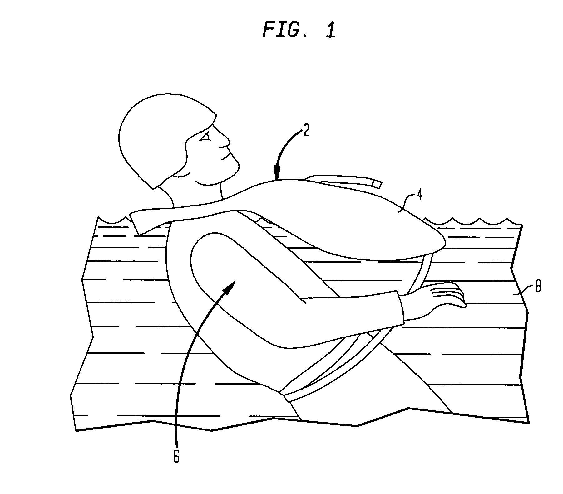
[0014]Referring now to FIG. 1, an individual flotation device 2 comprises a generally known construction including a flexible outer shell 4, composed of, e.g., a polymeric substance, and a central cavity 5 (FIG. 3) filled with a gaseous medium such as air (not shown). The flotation device 4 may be operated, as shown, by a soldier 6 who has been ejected from a downed aircraft (not shown) and is floating in a body of water 8.

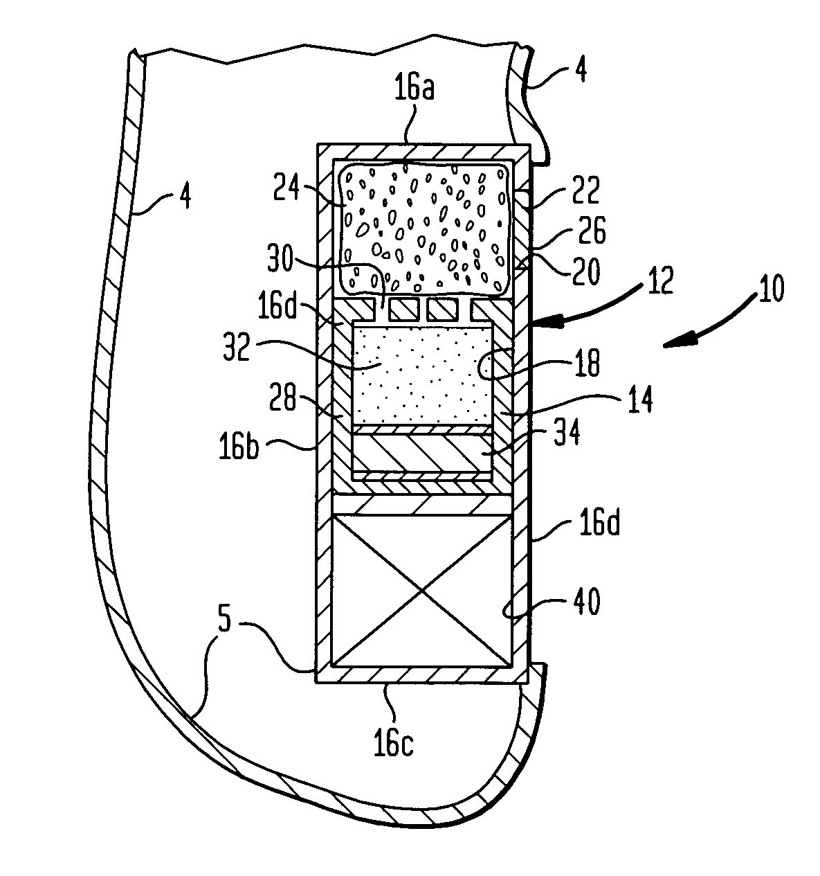
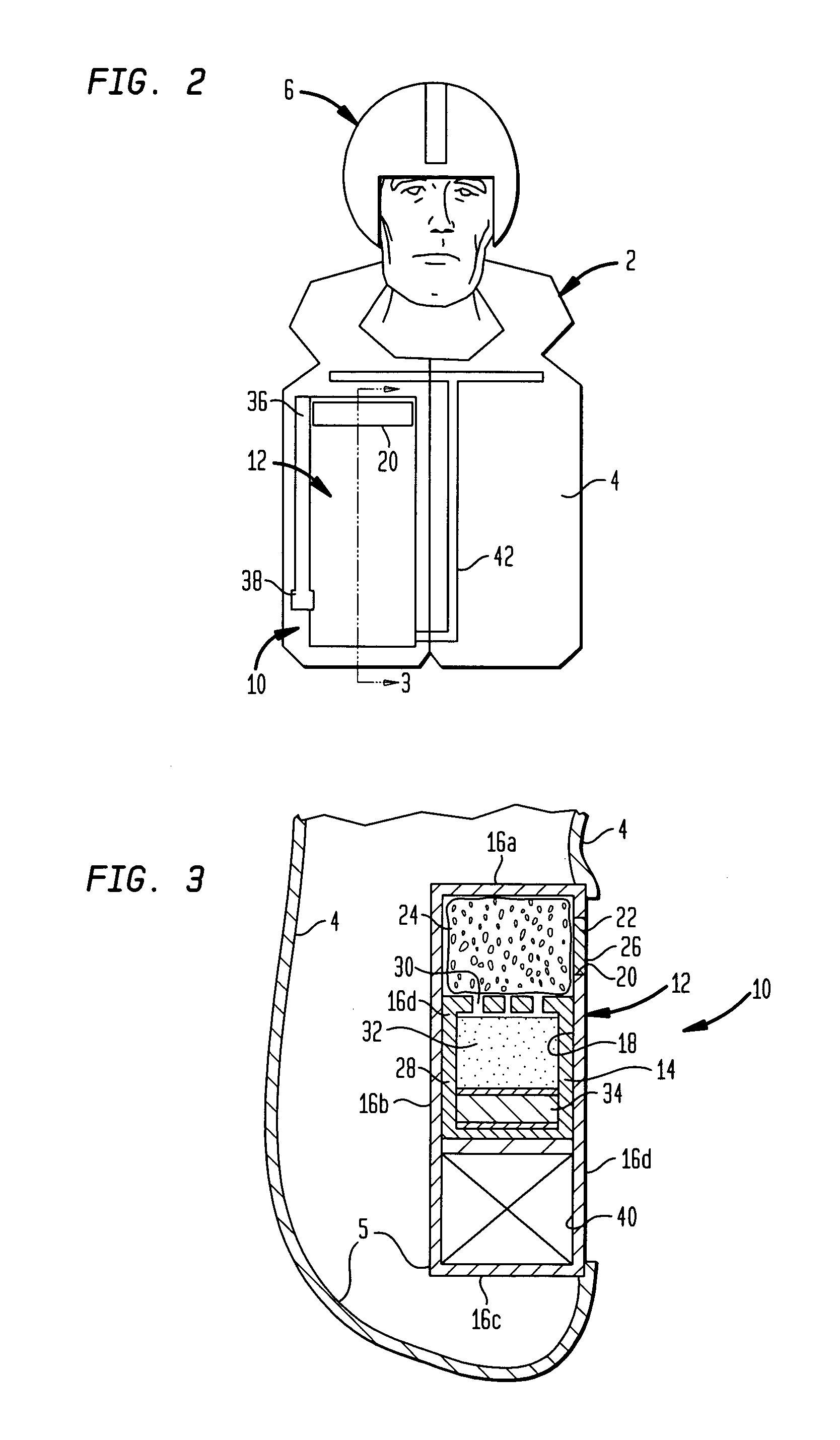
[0015]Referring now to FIGS. 2 and 3 and in accordance with one embodiment of the present invention, a metal air battery module is illustrated generally at 10. In this embodiment, the metal air battery module 10 comprises a housing 12 and a metal air battery 14.

[0016]The housing 12 may include a generally rectangular shape in cross section and ...


PUM


Abstract

An individual flotation device includes a shell that has a cavity for receiving air and a housing that is connected to the shell. The housing has a metal air battery compartment that is dimensioned and configured to receive a metal air battery and also has an aperture. The housing may be located on the shell such that the aperture will generally remain above water during use of the flotation device. A membrane that may comprise hydrophobic properties may be located within the aperture of the housing.

Description

GOVERNMENT INTEREST[0001]The invention described herein may be manufactured, used, imported, sold, and licensed by or for the Government of the United States of America without the payment of any royalty thereon or therefor.BACKGROUND OF THE INVENTION[0002]1. Field of the Invention[0003]The present invention relates generally to survival devices and, more particularly, to power sources for use with such devices.[0004]2. Related Art[0005]The Department of Defense has recently stated that the development of lightweight and longer lasting survival devices for fixed wing and rotary aircraft crews is a high priority. It has been found that, in general, a reduction in the weight of survival devices is beneficial both during normal operation and during emergency operation. In the case of normal operation, the wearer and the equipment benefits from a reduced weight through increased performance (especially for high performance aircraft) and, in the case of emergency operation, the wearer wi...

Claims


Application Information

Patent Timeline
Patent Type & Authority Patents(United States)
IPC IPC(8): B63C9/125B63C9/08
CPCB63C9/1255B63C9/21
Inventor LEUNG, FEE CHAN
Owner ARMY US SEC THE
Why Eureka
Try Eureka