Multihull hydrofoil watercraft

a multi-hull, watercraft technology, applied in the direction of foil-based vessels, special-purpose vessels, vessel construction, etc., can solve the problems of inability to fully electronic control systems, power consumption, weight, and complexity of fully electronic control systems

Inactive Publication Date: 2010-06-29
SALANI STEVEN JOHN
View PDF8 Cites 58 Cited by
  • Summary
  • Abstract
  • Description
  • Claims
  • Application Information

AI Technical Summary

Benefits of technology

[0013]As the boat picks up speed, the lifting force contributed by the foils will increase, causing the boat to move higher in altitude with respect to the ocean surface. At the same time, the lifting force contributed by the hulls will decrease as they are raised higher out of the water. The control mechanism will sense this shift in load on the hulls, and begin to decrease the angle of attack on the foils. At a point where the hulls are almost clear of the water the control system will achieve equilibrium, and the boat will continue to move forward with greatly reduced hull drag.
[0015]The current design minimizes the risk of capsize in both powered and sail craft. If a hull is lifted past the control mechanism's equilibrium point, the angle of attack on the foils will be reversed to provide negative lift to counteract the heeling force. This allows safe operation at higher speeds than would be possible in a conventional multihull craft.
[0016]The catamaran configuration may alternately use one controlled foil at the bow of each hull, and a fixed (non-adjustable) hydrofoil at the stern. This does not provide all the benefits of using two controlled foils per hull, but the cost and complexity of the craft is reduced.
[0017]A trimaran embodiment is similar to the z-hull discussed above, with the addition of a center hull. The control mechanisms in the outside hulls' hydrofoil assemblies regulate the boat's altitude and reduce risk of capsize in the same manner as the catamaran configuration.
[0019]To accommodate varying sea states the control system includes adjustable dampers that control the response time to changes in hull buoyancy. Thus the system can be tuned to provide the most comfortable and safe ride for the passengers.

Problems solved by technology

These performance enhancements have been limited by difficulties associated with the hydrofoil control mechanisms.
Previous applications of hydrofoils to sailcraft have also been limited in that the designs were effective only in high wind conditions.
For smaller powered vessels, or for sail boats in particular, the power consumption, weight, and complexity of fully electronic control systems is not as practical.
Previous designs for hydrofoil craft have not fully addressed all the requirements for a control system that accommodates varying weather, sea, and load conditions.
The design does not address altitude stabilization or automatically adjust for changing wind conditions or sail trim (“the wings may be actuated by means of control means that are accessible from the cockpit)”.
This design improves roll stabilization but does not exploit the lifting potential of the hydrofoils to reduce hull drag, nor does it attempt to control the altitude of the craft.
This design does not exploit the lifting potential of the hr drofoil, and is also very susceptible to localized variations in wave height that could adversely affect stability.
The catamaran stabilization structure of U.S. Pat. No. 4,561,371 (Kelley et al) employs passive wing structures whose angle of attack is fixed and therefore do not adjust to accommodate changing conditions.
The rudder foil does not employ the canard control mechanism, and is therefore less effective in counteracting any pitching motion that may be induced by wind / wave interaction.
The canard mechanisms on the lateral foils may also be susceptible to swamping by large waves which could destabilize the craft.

Method used


Image

  • Multihull hydrofoil watercraft
  • Multihull hydrofoil watercraft
  • Multihull hydrofoil watercraft

Examples


Embodiment Construction

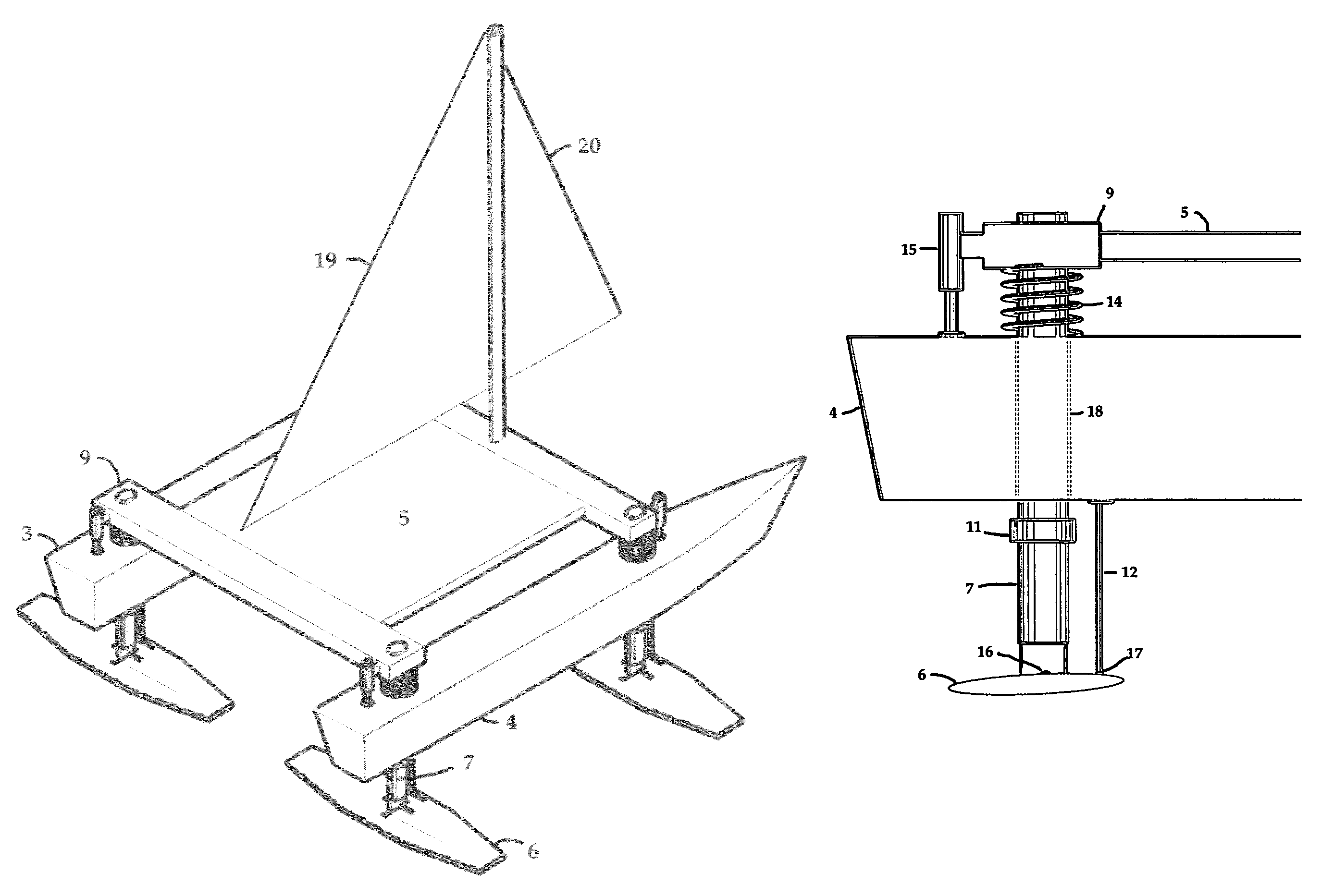
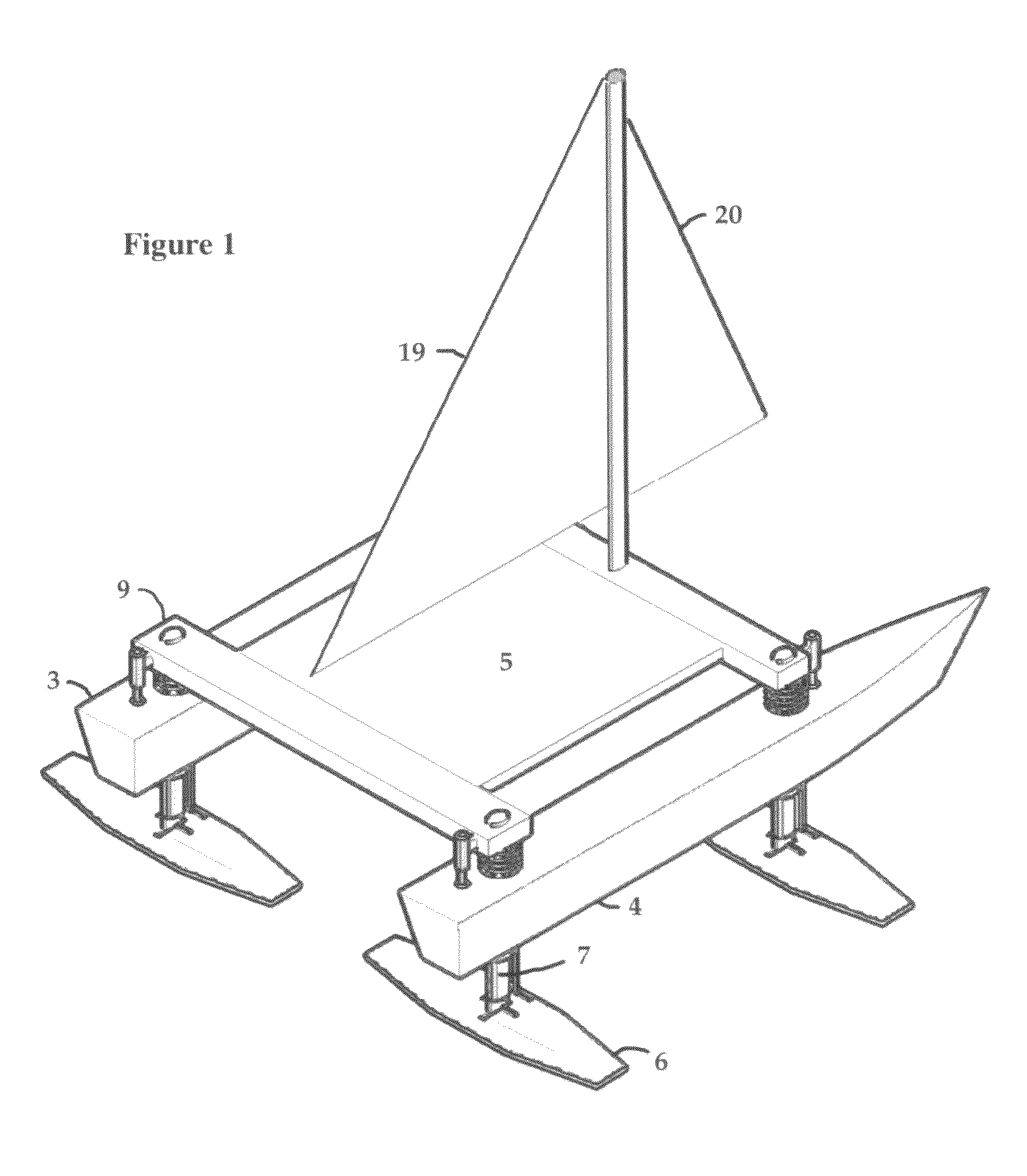
[0026]FIG. 1 illustrates the preferred embodiment of the preset invention in a catamaran sailboat configuration. Twin hulls 3 and 4 are connected via a deck structure 5 that accommodates passengers, equipment, and supplies. Cross beams 9 may be present to add strength and rigidity to the deck structure, but are not an essential element of the invention. A typical sail configuration will include a main sail 19 and jib 20, although any desired sail configuration is compatible with the present invention. A hydrofoil 6 is mounted near the forward and aft end of each hull, supported by a vertical strut 7.

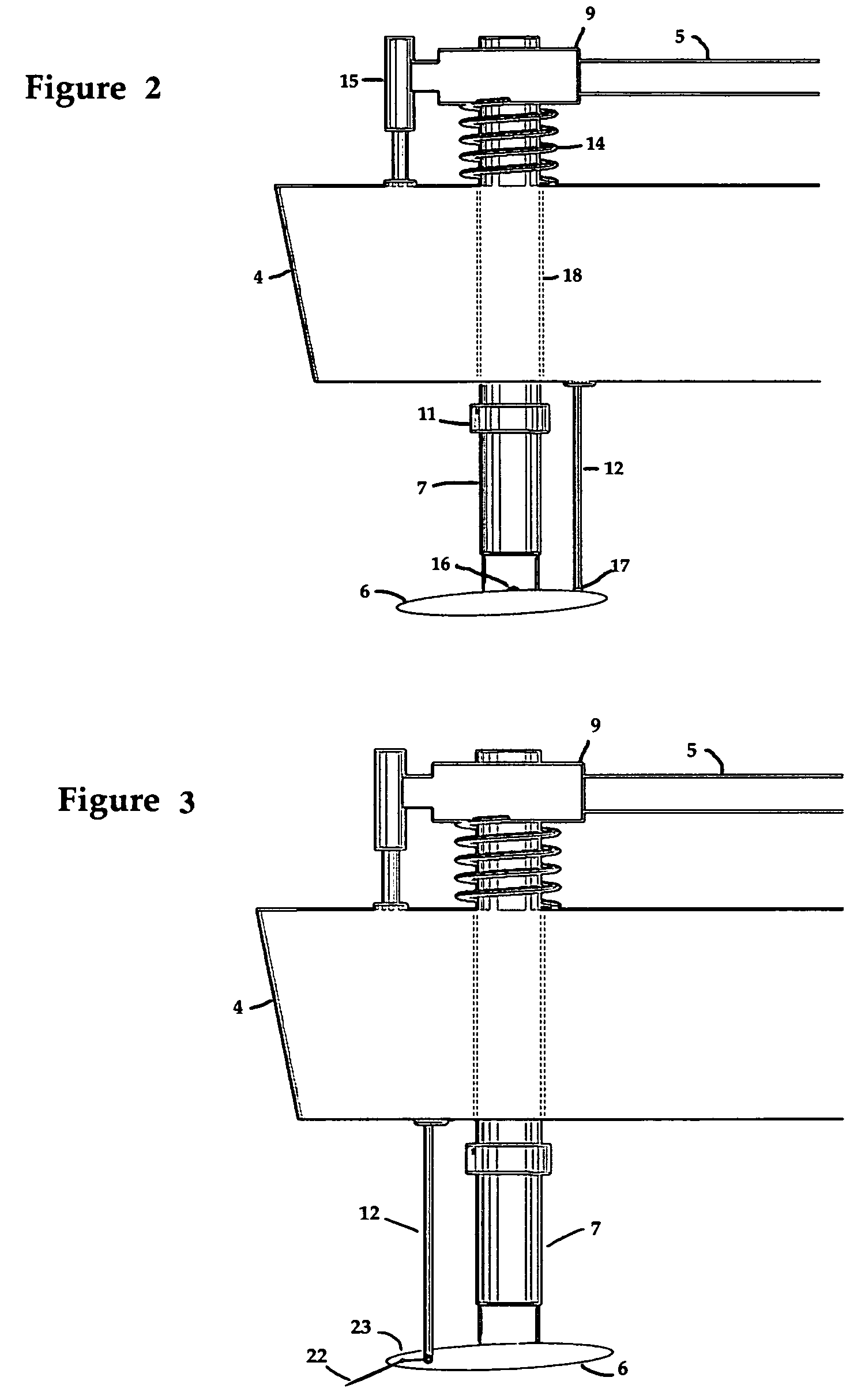
[0027]FIG. 2 is a detailed side view of the hydrofoil support and control mechanism. Each hydrofoil 6 is mounted on a pivot 16 which allows the foil's angle of attack to be adjusted by a control rod 12 attached to the foil at a pivot point 17. For illustration purposes the control rod is shown outside of the strut, but in practice could be enclosed within the strut to reduce drag as the ...


PUM


Abstract

A multihull hydrofoil watercraft incorporates a stabilization system wherein the buoyancy of the hulls is used as a sensing and control mechanism for the hydrofoils. The use of hull buoyancy to adjust the hydrofoil lift provides for automatic control of altitude, pitch and roll, and allows the craft to accommodate varying weather and sea conditions while providing a smooth ride for passengers. The stabilization technique eliminates the need for extraneous sensing mechanisms placed in or on the water surface which are subject to fouling, damage, or disruption by localized surface disturbances.

Description

CROSS REFERENCE TO RELATED APPLICATIONS[0001]This application claims priority to provisional case 60 / 857,720 filed Nov. 8, 2006BACKGROUND OF THE INVENTION[0002]The development of the hydrofoil lifting device has the potential to greatly advance the performance of watercraft. Both powered and sail craft may benefit from the application of the hydrofoil device. These performance enhancements have been limited by difficulties associated with the hydrofoil control mechanisms. Previous applications of hydrofoils to sailcraft have also been limited in that the designs were effective only in high wind conditions.[0003]For large powered watercraft, fully electronic control mechanisms have been developed to optimize performance and stability under varying weather and sea conditions. For smaller powered vessels, or for sail boats in particular, the power consumption, weight, and complexity of fully electronic control systems is not as practical. The present invention offers many of the advant...

Claims


Application Information

Patent Timeline
Patent Type & Authority Patents(United States)
IPC IPC(8): B63B1/00B63B1/14B63B1/10B63B39/06B63B39/00B63B1/28B63B1/24
CPCB63B1/14B63B1/242B63B39/061B63B17/0081B63B39/06B63B1/285
Inventor SALANI, STEVEN JOHN
Owner SALANI STEVEN JOHN
Why Eureka
Try Eureka