Reciprocating fluid energy device

Active Publication Date: 2017-08-15
BURKE THOMAS J
View PDF28 Cites 6 Cited by
  • Summary
  • Abstract
  • Description
  • Claims
  • Application Information

AI Technical Summary

Benefits of technology

[0035]Devices with high velocity foils create tremendous turbulence and inefficiency when interfacing with slow moving fluids. Efficiency in this setting requires a large surface area foil moving at a speed not significantly different than the moving fluid itself. The present invention provides just such a low velocity/high surface area solution for settings such as hydro-kinetic power or wind energy.
[0036]Previous fluid-energy devices have relied either on high velocity fluid such as wind turbines or high pressure fluid such as hydro-electric power. There can be significant kinetic energy in the movement of slow moving fluids if the fluid is of significant volume or density. The current known art has not been abl

Problems solved by technology

This technology has been limited to locations where there was a significant vertical drop for the water.
These systems cause significant alteration of the landscape and the eco-system.
These factors limit the potential growth of conventional hydro-power.
The advancing technology of ever-larger turbines has made this economically viable but it is still limited to locations where there is sufficient average wind speed.
Many devices have been tested but they remain economically competitive only where the price of energy is extremely high.
This results in significant turbulence and ineff

Method used


Image

  • Reciprocating fluid energy device
  • Reciprocating fluid energy device
  • Reciprocating fluid energy device

Examples


Embodiment Construction

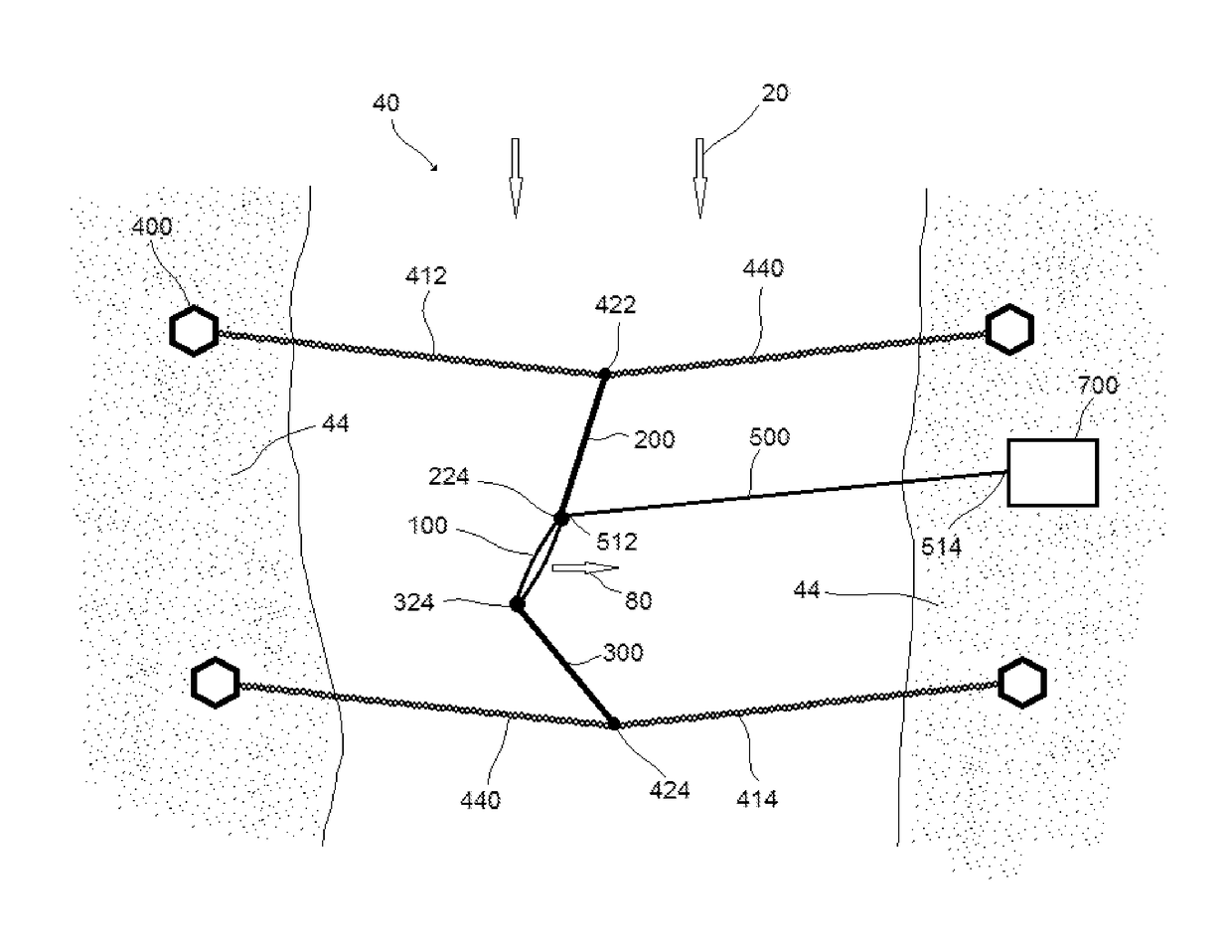
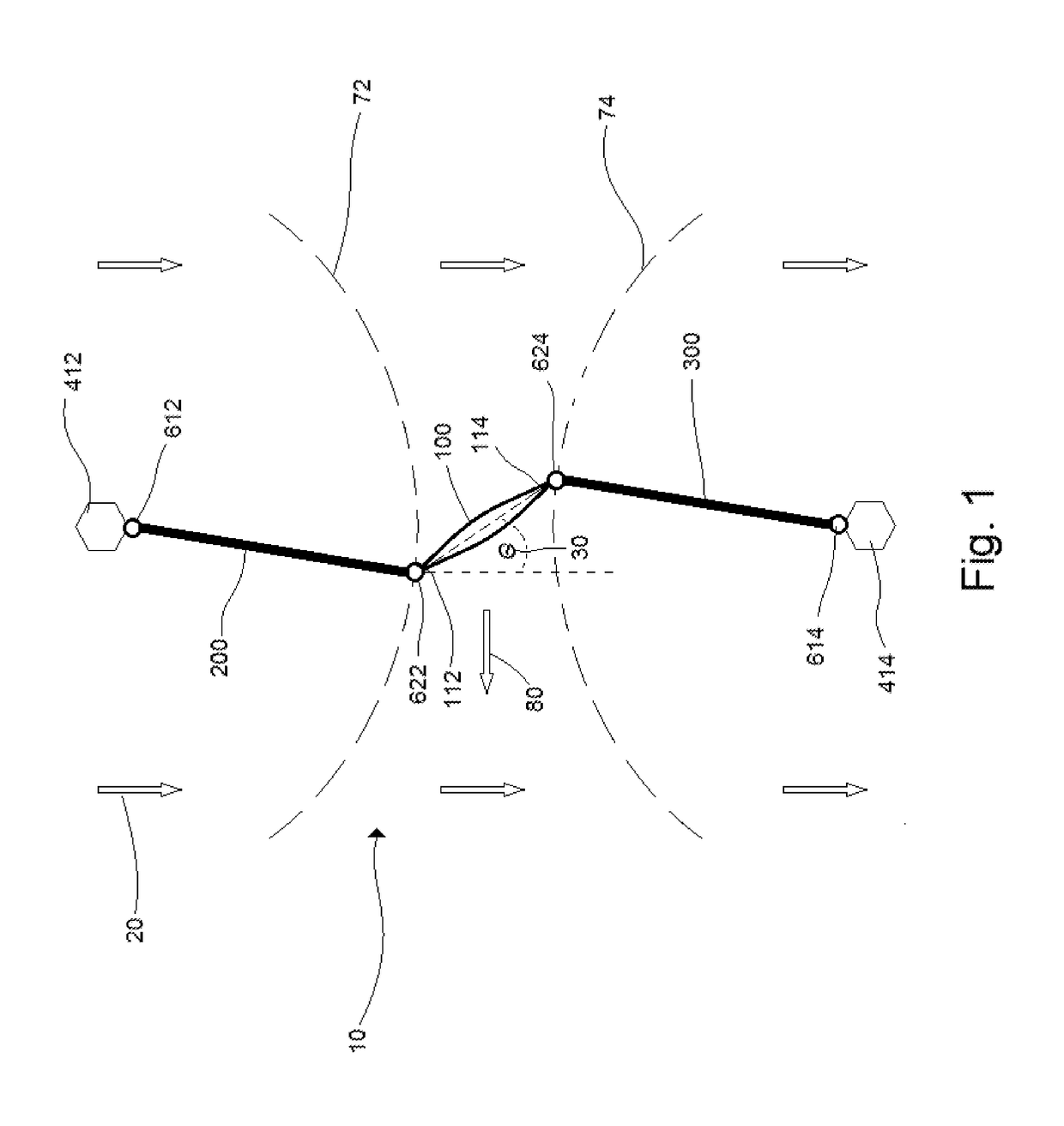
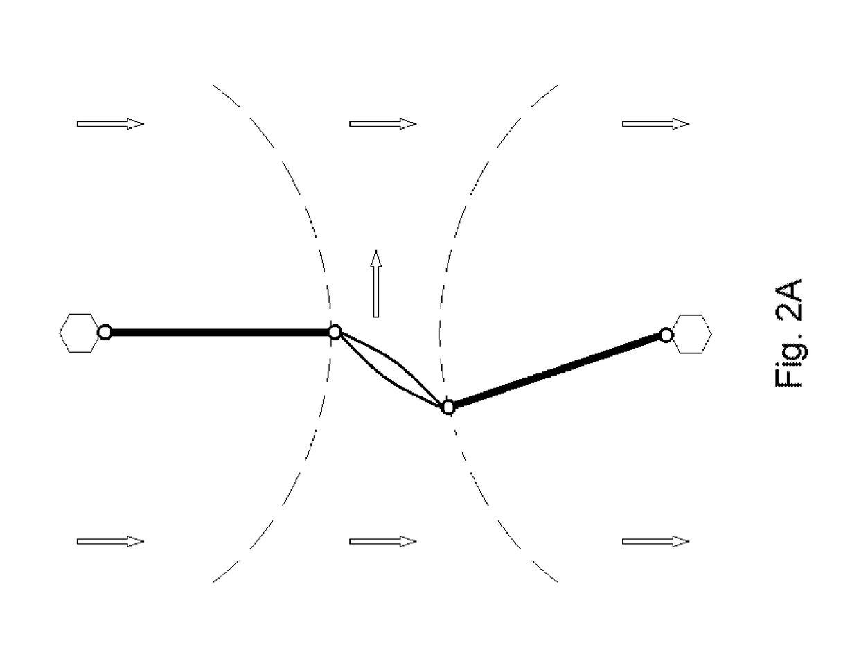
[0056]In one embodiment, the present invention discloses a reciprocating device 10 for extracting energy from a fluid flow 20. The fluid flow 20 may be water, air, or any other fluid. The device 10 comprises a foil 100, an upstream support member 200, a downstream support member 300, and a frame 400. Optionally, it also comprises a force transfer mechanism 500 and a generator 700.

[0057]A foil creates lift when fluid passes over its surfaces. The leading edge of the foil splits the fluid, with one component of the split fluid running along one surface of the foil and a second component of the split fluid running along the opposite surface of the foil. When the foil is angled relative to the direction of fluid flow (the “angle of attack”), the component of the fluid passing over the surface of the foil angled away from the direction of fluid flow moves faster than the component of the fluid passing over the surface of the foil angled towards the direction of fluid flow. Because of the...


PUM


Abstract

A reciprocating fluid-energy device to be used in a flowing fluid, having a foil, an upstream support member, a downstream support member, and a frame, where the frame retains the device in place within the flowing fluid, the support members movably attach the foil to the frame, and the foil moves laterally back and forth across the direction of the flow of the fluid, with changes in direction of the movement of the foil occurring automatically and spontaneously without external intervention other than the force of the flowing fluid.

Description

BACKGROUND[0001]1. Technical Field[0002]The present invention relates generally to power producing devices and, more particularly, to a low-speed, low-pressure fluid-energy device that captures kinetic energy from the movement of fluid by the use of one or more reciprocating foils.[0003]2. Description of Prior Art[0004]Humans have long derived energy from flowing wind or water. The first great human machines were reciprocating air foils or what are commonly known as sailing ships. Water wheels and windmills represent some of the first machines deriving energy from non-animals sources. Hydro-power became a mature technology in the 1900s. Modern hydro-power has relied on high pressure / high head systems often associated with a dam or a reservoir. This technology has been limited to locations where there was a significant vertical drop for the water. These systems cause significant alteration of the landscape and the eco-system. These factors limit the potential growth of conventional h...

Claims


Application Information

Patent Timeline
IPC IPC(8): F03B13/00F03B17/06H02P9/04F03B13/10
CPCF03B17/06F03B13/10F03B13/264F03D5/06F05B2210/16F05B2240/91F05B2240/931Y02E10/30Y02E10/20
Inventor BURKE, THOMAS J.
Owner BURKE THOMAS J
Why Eureka
Try Eureka