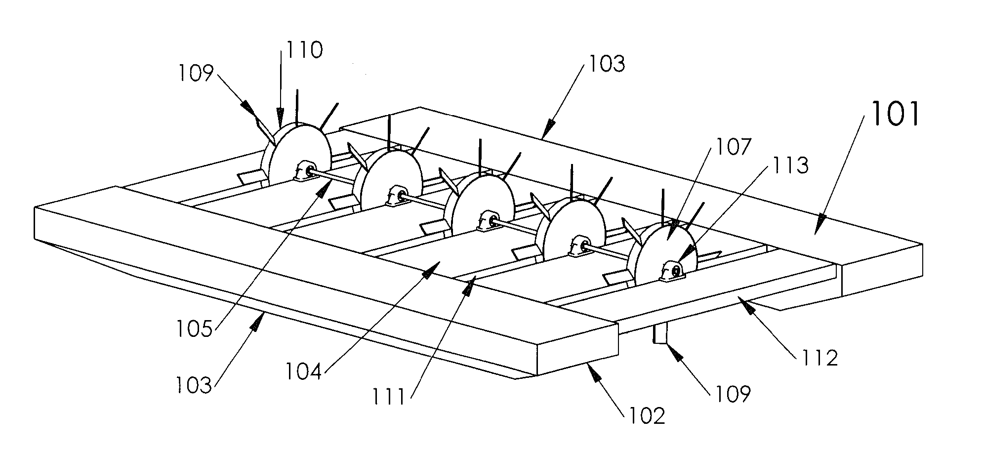
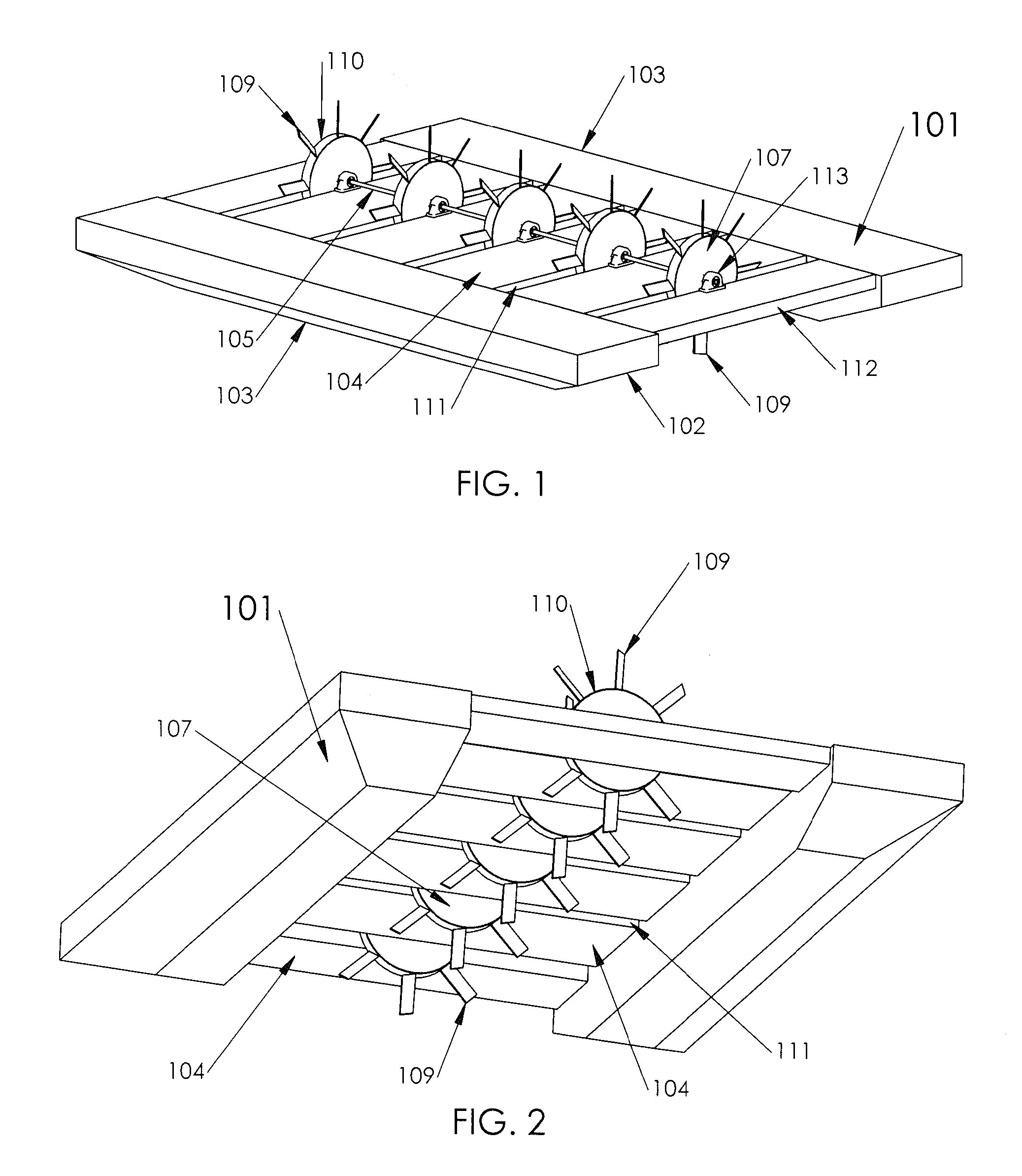
[0005]The present invention is directed towards a floating tidal generator that includes a floating structure and a plurality of rotors that are mounted on a shaft. The floating structure is secured to a stationary surface which can be a
mooring or a portion of land so that the
tidal water flows under the floating structure. The rotors have pitched blades that have a high
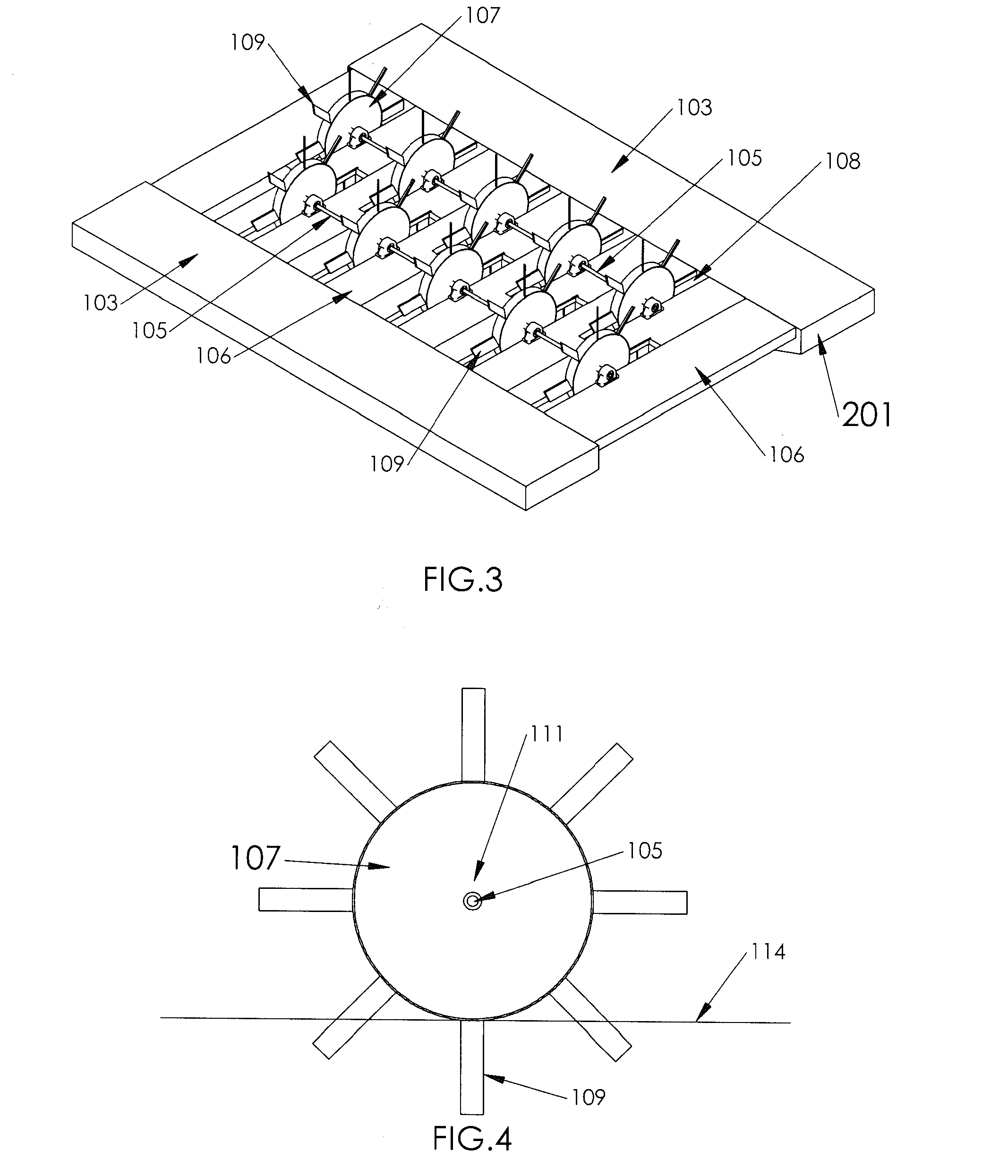
aspect ratio and extend radially outward from the centers of the rotors. The
aspect ratio defines the relationship between the blade span “b” and the blade area “S” by the equation
aspect ratio b2 / S. In an embodiment, the aspect ratio of the blades is equal to or greater than 2.0. The shaft and most of the rotors are suspended above the water with only a lower portion of the rotor blades submerged. The movement of the water causes the rotor blades to rotate about the shaft. Thus, each of the blades pierces the water, travels through the water and then emerges from the water during each rotation of the rotor. The shaft can be coupled to an electrical generator that transmits electrical power through an
underwater or floating cable to
shore. One of the main advantages of surface piercing rotor blades is that since the blades are above the water line, they are easily cleaned of marine growth without having to remove the blades from the tidal generator. This eliminates or greatly reduces the need for toxic anti-
fouling paints or other anti-
fouling surface treatments as well as complex and costly maintenance required to regularly clean and paint the
turbine blades of a fully submerged tidal generator.
[0006]In an embodiment, the flow of the water under the tidal generator can be aligned with the shaft. When the shaft is aligned with the flow of the water, the water will contact the first rotor and subsequently, the water will flow through all downstream rotors. As the water flows across the rotor blades, there is a reduction in the
water velocity resulting from the extraction of
kinetic energy from the upstream rotor as well as some turbulence is produced. This reduction in
water velocity will reduce the power that can be applied to the blades of the subsequent rotors. At the last rotor, the water velocity will be slower and the turbulence will be higher.
[0010]In yet another embodiment, the rotors can be coupled to a
wide diameter tube that provides
buoyancy to partially support the tidal generator. Rather that having individual rotors coupled to the shaft, the rotors blades are coupled directly to the outer
diameter of the tube. In this embodiment, the stationary structures are located at the ends of the tube and keels can extend from the bottoms of the stationary structures. The flow of water over the keels provides stability to keep the ends of the structure stable and the keels can be weighted to provide additional stability. The stationary structures can be coupled by an elongated member that extends through the center of the tube.
[0011]In order to minimize the reduction in water velocity and reduce the turbulence of the water flowing to the downstream rotors, the shaft can be angled relative to the flow of the water. By angling the shaft, the rotors on the shaft are offset and much of the loss in velocity and turbulence produced by the leading rotors will not flow directly into the subsequent downstream rotors. In order to hold the tidal generator at an angle to the
water flow, the
front and back ends of the tidal generator can be coupled to one or more moorings.
[0014]Even if the
pitch angle if fixed, it is possible to alter the
attack angle of the blades to the water by moving the angle to the rotors to the
water flow direction. The normal
pitch can be set for water flowing directly under the shaft. By changing the angle of the shaft, the
attack angle of the blades is altered. In an embodiment, the tidal generator can be configured to alter the
pitch to keep the rotational velocity of the shaft within a predetermined range. Thus, at low water velocity, the shaft angle is moved to increase the
attack angle of the blades and as the water velocity increases, the shaft is moved to decrease the
angle of attack. By decreasing the
angle of attack, the lift forces on the blades are decreased which can prevent damage to the tidal generator.
[0015]The inventive tidal generator has numerous advantages over the prior art tidal generator systems. The design is simplified because the
drive shaft, bearing and generator are above the water line and only the lower rotors blades and the floating structure are submerged. Since the main generator components are above water, there are no complicated seals or
underwater mechanisms that can leak and cause a
system failure. The tidal generator is also more easily moved to the installation site. The tidal generator is towed to an installation site and secured to a fixed object such as a
mooring coupled to the sea floor or a portion of land. Thus, there is no need to
mount the entire tidal generator
underwater which requires specialized installation equipment including cranes and divers working in a high water velocity area. When maintenance is required, the inventive tidal generator can be towed to a dock for repairs. In contrast, when a submerged tidal generator needs to be repaired, it may need to be removed from the sea floor which can be very difficult. In summary, the inventive tidal generator is simpler and
safer system that will made
tidal power more accessible.

