Rotating control device docking station

a technology of rotating control device and docking station, which is applied in the direction of survey, sealing/packing, borehole/well accessories, etc., and can solve the problems of differential sticking, and increasing the probability of well control problems

Active Publication Date: 2011-04-19
WEATHERFORD TECH HLDG LLC
View PDF527 Cites 125 Cited by
  • Summary
  • Abstract
  • Description
  • Claims
  • Application Information

AI Technical Summary

Benefits of technology

[0024]A system and method for converting a drilling rig from conventional hydrostatic pressure drilling to managed pressure drilling or underbalanced drilling is disclosed that utilizes a docking station housing. The docking station housing is mounted on a marine riser or bell nipple. The housing may be positioned above the surface of the water. A rotating control device can be moved through the well center with a remote hydraulically activated running tool and remotely hydraulically latched. The rotating control device can be interactive so as to automatically and remotely lubricate and cool from the docking station housing while providing other information to the operator. The system may be compatible with different rotating control devices and typical drilling equipment. The system and method allow for conversion between managed pressure drilling or underbalanced drilling to conventional drilling as needed, as the rotating control device can be remotely latched to or unlatched from the docking station housing and moved with a running tool or on a tool joint. A containment member allows for conventional drilling after the rotating control device is removed. A docking station housing telescoping or slip joint in the containment member both above the docking station housing and above the surface of the water reduces the need for a riser slip joint or its typical function in the marine riser.

Problems solved by technology

Although operating companies may have different internal criteria for determining safe and economic drill-ability of prospects in their lease portfolio, few would disagree that a growing percentage are considered economically undrillable with conventional techniques.
In fact, the U.S. Department of the Interior has concluded that between 25% and 33% of all remaining undeveloped reservoirs are not drillable by using conventional overbalanced drilling methods, caused in large part by the increased likelihood of well control problems such as differential sticking, lost circulation, kicks, and blowouts.
However, this eliminates its ability to compensate for the relative movement between the marine riser and the floating rig.
Such riser slips joints are expensive to purchase, and expensive to maintain and repair as the seals often have to be replaced.
Pore pressure depletion, the hydraulics associated with drilling in deeper water, and increasing drilling costs indicate that the amount of known resources considered economically undrillable with conventional techniques will continue to increase.

Method used


Image

  • Rotating control device docking station
  • Rotating control device docking station
  • Rotating control device docking station

Examples


Embodiment Construction

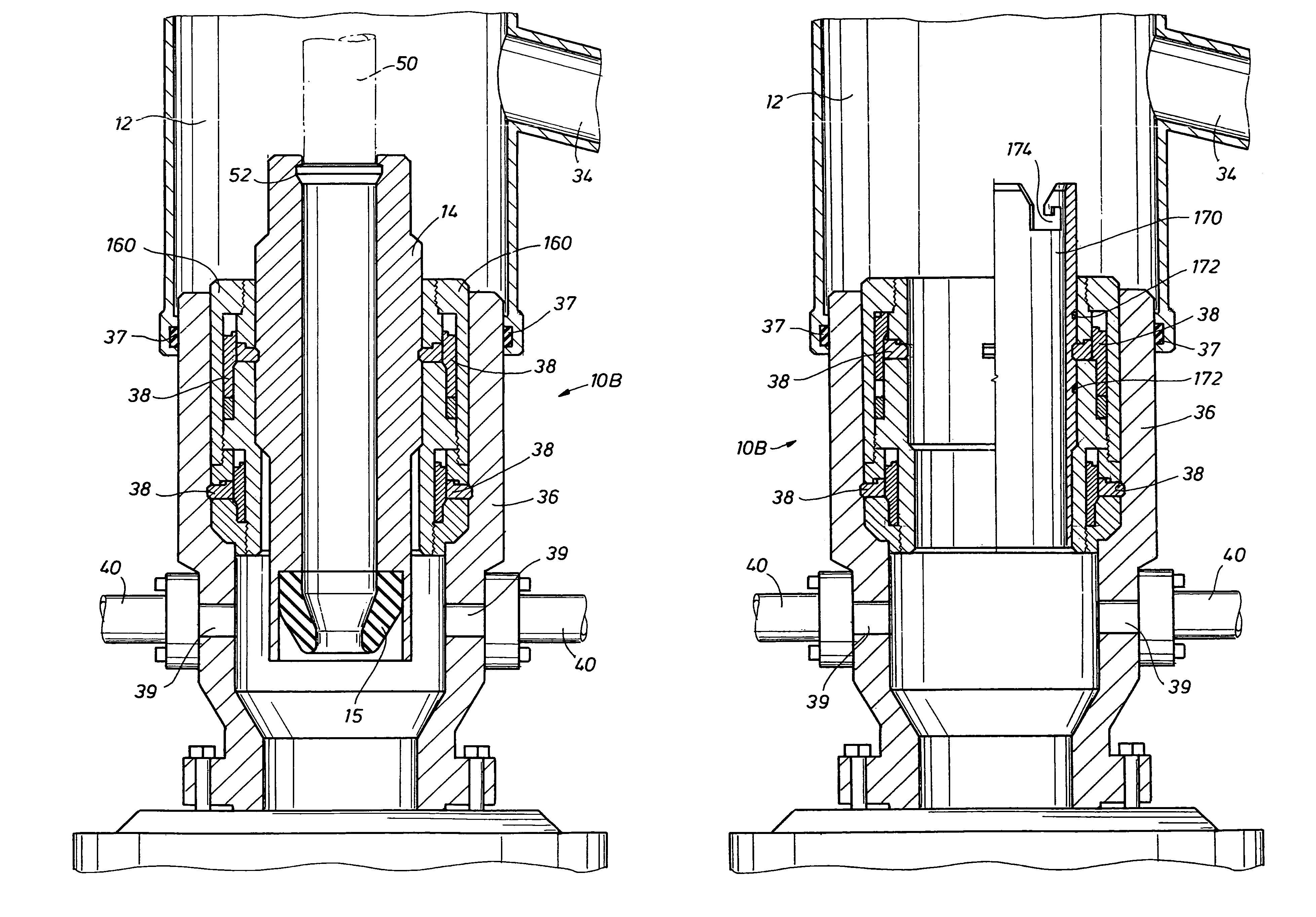
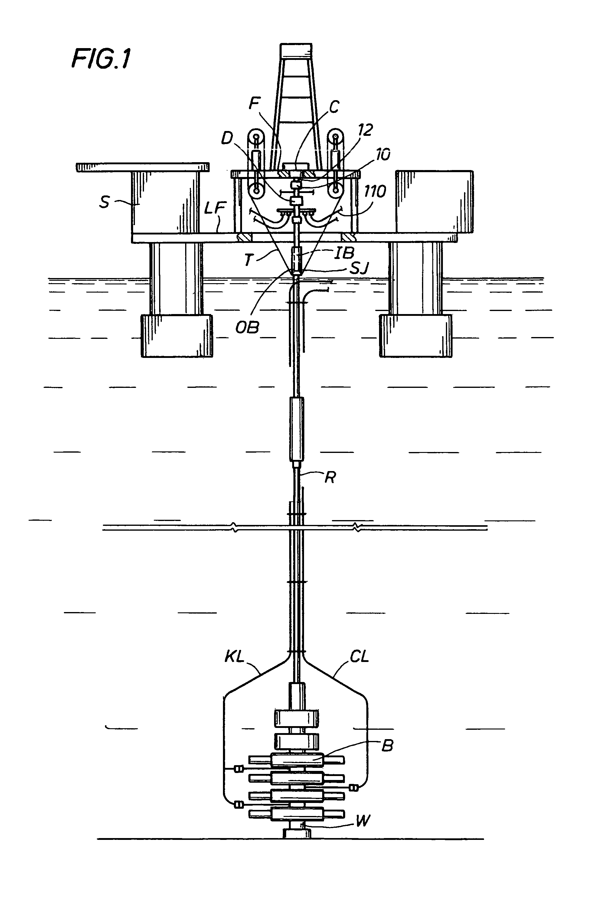
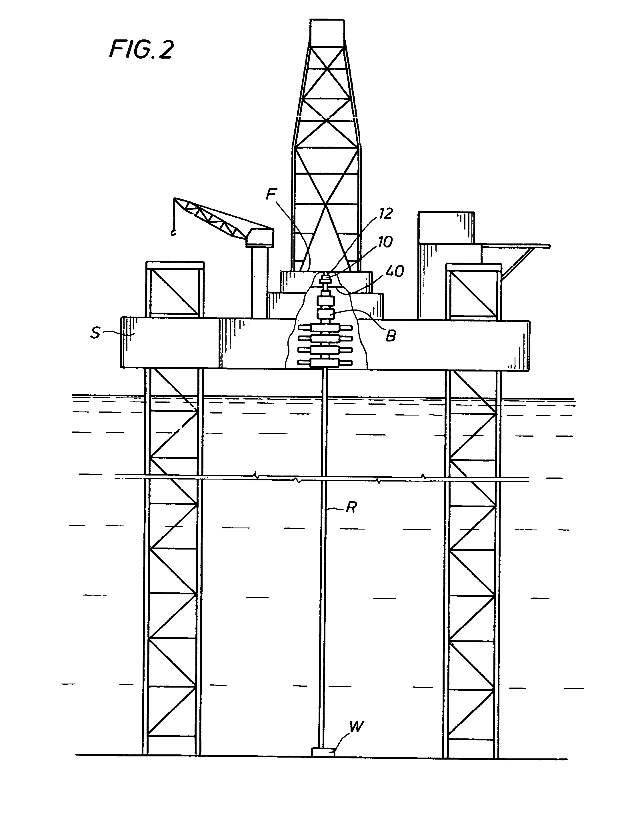
[0044]Generally, the present invention involves a system and method for converting an offshore and / or land drilling rig or structure S between conventional hydrostatic pressure drilling and managed pressure drilling or underbalanced drilling using a docking station housing, designated as 10 in FIGS. 1 and 2. As will be discussed later in detail, the docking station housing 10 has a latching mechanism. The housing is designated in FIGS. 3 to 13 as 10A, 10B, or 10C depending on the latching mechanism contained in the housing. The docking station housing 10 is designated as 10A if it has a single latching assembly (FIG. 6A), as 10B if it has a dual latching assembly (FIG. 4B), and as 10C if it has a J-hooking latching assembly (FIG. 8). It is contemplated that the three different types of latching assemblies (as shown with housing 10A, 10B, and 10C) can be used interchangeably. As will also be discussed later in detail, the docking station housing 10 at least provides fluid, such as ga...


PUM


Abstract

A system and method is provided for converting a drilling rig between conventional hydrostatic pressure drilling and managed pressure drilling or underbalanced drilling using a docking station housing mounted on a marine riser or bell nipple. This docking station housing may be positioned above the surface of the water. When a removable rotating control device is remotely hydraulically latched with the docking station housing, the system and method allows for interactive lubrication and cooling of the rotating control device, as needed, along with a supply of fluid for use with active seals.

Description

CROSS-REFERENCE TO RELATED APPLICATIONS[0001]This application is a continuation-in-part of application Ser. No. 10 / 995,980 filed Nov. 23, 2004 now U.S. Pat. No. 7,487,837, which Application is hereby incorporated by reference for all purposes in its entirety.[0002]This application is a continuation-in-part of application Ser. No. 11 / 366,078 filed Mar. 2, 2006 now U.S. Pat. No. 7,836,946, which is a continuation-in-part of application Ser. No. 10 / 995,980 filed on Nov. 23, 2004 now U.S. Pat. No. 7,487,837, which Applications are hereby incorporated by reference for all purposes in their entirety.[0003]This application claims the benefit of provisional Application No. 60 / 921,565 filed Apr. 3, 2007, which Application is hereby incorporated by reference for all purposes in its entirety.STATEMENT REGARDING FEDERALLY SPONSORED RESEARCH OR DEVELOPMENT[0004]N / AREFERENCE TO MICROFICHE APPENDIX[0005]N / ABACKGROUND OF THE INVENTION[0006]1. Field of the Invention[0007]This invention relates to th...

Claims


Application Information

Patent Timeline
Patent Type & Authority Patents(United States)
IPC IPC(8): E21B41/04
CPCE21B21/08E21B23/02E21B33/085E21B19/004E21B21/001E21B34/16Y10S285/92E21B2021/006E21B21/085E21B7/12E21B41/0007E21B44/00
Inventor BAILEY, THOMAS F.HANNEGAN, DON M.CHAMBERS, JAMES W.WAGONER, DANNY W.
Owner WEATHERFORD TECH HLDG LLC
Why Eureka
Try Eureka