Infusion array ablation apparatus
a technology of ablation apparatus and array, which is applied in the direction of prosthesis, catheter, therapy, etc., can solve the problems of poor localization, large damage to healthy tissue, and high heat generation
Inactive Publication Date: 2006-12-19
ANGIODYNAMICS INC
View PDF72 Cites 46 Cited by
- Summary
- Abstract
- Description
- Claims
- Application Information
AI Technical Summary
Benefits of technology
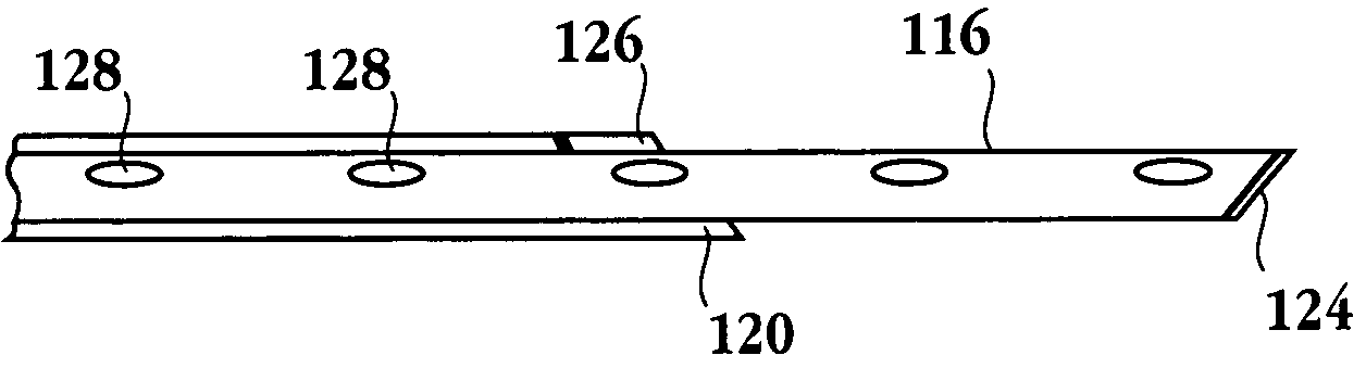
[0022]An electrode template can be positioned at the distal end of the delivery catheter. It assists in guiding the deployment of the electrodes to a surrounding relationship at an exterior of a selected mass in a tissue. The electrodes can be hollow. An adjustable electrode insulator can be positioned in an adjacent, surrounding relationship to all or some of the electrodes. The electrode insulator is adjustable, and capable of being advanced and retracted along the electrodes in order to define an electrode conductive surface.
Problems solved by technology
Current open procedures for treatment of tumors are extremely disruptive and cause a great deal of damage to healthy tissue.
During the surgical procedure, the physician must exercise care in not cutting the tumor in a manner that creates seeding of the tumor, resulting in metastasis.
Among the problems associated with all of these procedures is the requirement that highly localized heat be produced at depths of several centimeters beneath the surface of the body.
However, the extent of localization is generally poor, with the result that healthy tissue may be harmed.
Induction heating gives rise to poor localization of the incident energy as well.
When it is driven using RF current unwanted surface heating occurs diminishing heating to the underlying tissue.
Thus, non-invasive procedures for providing heat to internal tumors have had difficulties in achieving substantial specific and selective treatment.
In thermotherapy, heat energy of greater than 45 degrees C. is applied, resulting in histological damage, desiccation and the denaturization of proteins.
It is difficult to externally induce hyperthermia in deep body tissue because current density is diluted due to its absorption by healthy tissue.
Additionally, a portion of the RF energy is reflected at the muscle / fat and bone interfaces which adds to the problem of depositing a known quantity of energy directly on a small tumor.
Attempts to use interstitial local hyperthermia have not proven to be very successful.
This process has been difficult to achieve due to a variety of factors including, (i) positioning of the RF ablation electrodes to effectively ablate all of the mass, (ii) introduction of the RF ablation electrodes to the tumor site and (iii) controlled delivery and monitoring of RF energy to achieve successful ablation without damage to non-tumor tissue.
Method used
View moreImage
Smart ImageViewing Examples

Examples
example 1
[0143]
Exposed electrode length:1.5cmDistance between electrodes:1.5cmPower setting:5WAblation time:10min.Lesion size:width:2cmlength:1.7cmdepth:1.5cm
example 2
[0144]
Exposed electrode length:1.5Distance between electrodes:2.0Power setting:7.0Ablation time:10min.Lesion size:width:2.8cmlength:2.5cmdepth:2.2cm
example 3
[0145]
Exposed electrode length:2.5cmDistance between electrodes:2.0cmPower setting:10WAblation time:10minLesion size:width:3.0cmlength:2.7cmdepth:1.7cm
Login to view more PUM
| Property | Measurement | Unit |
|---|---|---|
| microwave energy | aaaaa | aaaaa |
| power | aaaaa | aaaaa |
| pressure | aaaaa | aaaaa |
Abstract
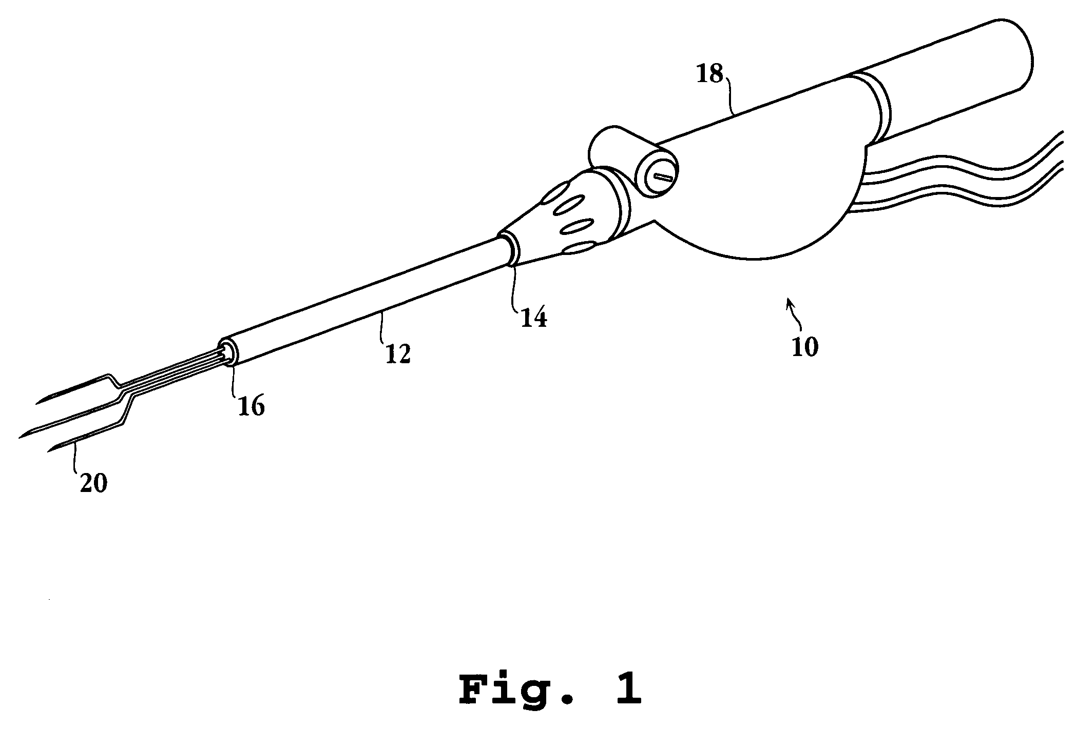
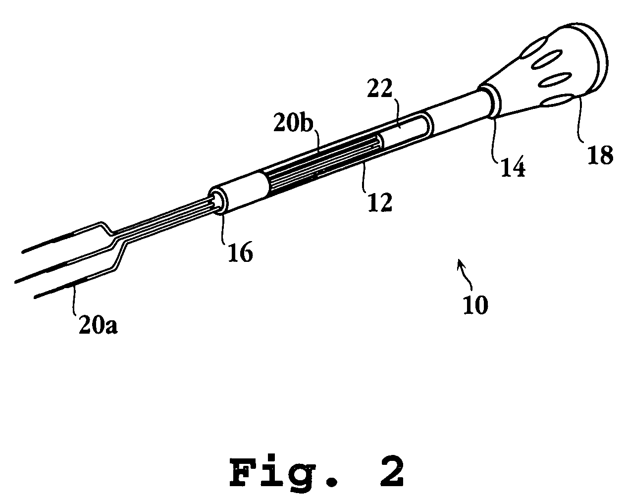
An infusion array ablation apparatus includes an elongated delivery device having a lumen and an infusion array positionable in the lumen. The infusion array includes an RF electrode and at least a first and a second infusion member. Each infusion member has a tissue piercing distal portion and an infusion lumen. At least one of the first or second infusion members is positionable in the elongated delivery device in a compacted state and deployable from the elongated delivery device with curvature in a deployed state. Also, at least one of the first or second infusion members exhibits a changing direction of travel when advanced from the elongated delivery device to a selected tissue site. At least one infusion port is coupled to one of the elongated delivery device, the infusion array, the first infusion member or the second infusion member.
Description
[0001]This application is a continuation of U.S. patent application Ser. No. 09 / 513,725, filed Feb. 24, 2000, now U.S. Pat. No. 6,641,580, which is a continuation-in-part of U.S. patent application Ser. No. 09 / 383,166, filed Aug. 25, 1999, now U.S. Pat. No. 6,471,698, which is a continuation of U.S. patent application Ser. No. 08 / 802,195, filed Feb. 14, 1997, now U.S. Pat. No. 6,071,280, which is a continuation-in-part of U.S. patent application Ser. No. 08 / 515,379, filed Aug. 15, 1995, now U.S. Pat. No. 5,683,384, which is a continuation-in-part of U.S. patent application Ser. No. 08 / 290,031, filed Aug. 12, 1994, now U.S. Pat. No. 5,536,267, which is a continuation-in-part of U.S. patent application Ser. No. 08 / 148,439, filed Nov. 8, 1993, now U.S. Pat. No. 5,458,597, all of which are incorporated herein by reference.[0002]The Ser. No. 09 / 513,725 application is also a continuation-in-part of U.S. patent application Ser. No. 09 / 364,203, filed Jul. 30, 1999, now U.S. Pat. No. 6,663,6...
Claims
Login to view more Application Information
Patent Timeline
 Patent Type & Authority Patents(United States)
IPC IPC(8): A61B18/18A61B17/00A61B18/00A61B18/12A61B18/14A61B18/22A61M3/02A61M25/00A61N1/40A61N5/04C22C1/04C22C14/00C22F1/18
CPCA61B18/1477A61B18/1482A61B18/18A61B18/1815A61N1/403A61N5/02A61N5/045C22C1/0491C22C14/00C22F1/183B22F3/1216C22C33/0285A61B18/1206A61B18/14A61B18/1402A61B18/1485A61B18/1492A61B2017/00026A61B2017/00084A61B2017/00101A61B2018/00011A61B2018/00023A61B2018/00196A61B2018/00273A61B2018/00452A61B2018/00476A61B2018/00577A61B2018/00642A61B2018/00666A61B2018/00678A61B2018/00702A61B2018/00708A61B2018/00726A61B2018/00744A61B2018/00761A61B2018/00779A61B2018/00791A61B2018/00797A61B2018/00821A61B2018/00827A61B2018/00875A61B2018/00892A61B2018/124A61B2018/1253A61B2018/126A61B2018/1425A61B2018/143A61B2018/1432A61B2018/1435A61B2018/1472A61B2018/162A61B2018/1861A61B2218/002A61M3/0279A61M25/007A61N1/06A61N5/04B22F2999/00C22C1/047
Inventor EDWARDS, STUART D.BAKER, JAMESSHARKEY, HUGHLAX, RONALD G.
Owner ANGIODYNAMICS INC
- R&D Engineer
- R&D Manager
- IP Professional
Why Eureka
- Industry Leading Data Capabilities
- Powerful AI technology
- Patent DNA Extraction
Try Eureka
Browse by: Latest US Patents, China's latest patents, Technical Efficacy Thesaurus, Application Domain, Technology Topic.
© 2024 PatSnap. All rights reserved.Legal|Privacy policy|Modern Slavery Act Transparency Statement|Sitemap