Moveable animated display device

a display device and moving technology, applied in the field of display devices, can solve the problems of affecting the observer's ability to perceive the display image, affecting the accuracy of the display image, so as to achieve accurate registration and close contact, flat and compact configuration, and the effect of accurate registration

Active Publication Date: 2006-12-19
SEDER RUFUS BUTLER
View PDF22 Cites 67 Cited by
  • Summary
  • Abstract
  • Description
  • Claims
  • Application Information

AI Technical Summary

Benefits of technology

[0012]A more particular object of the invention is to provide a moveable display device that can achieve a relatively flat and compact configuration.
[0013]A further object of the invention is to provide a moveable display device that achieves and maintains accurate registration and close contact between a shutter element layer and a coded image layer.
[0016]Yet another object of particular embodiments of the invention is to accomplish these goals in a moveable display device that is can be simple in structure, operation, and manufacture.

Problems solved by technology

Lack of complete contact between the shutter elements and the coded images creates thin air pockets between the layers thereby creating undesirable shadows that diminish the observer's ability to perceive the display image.
Incomplete contact also results in an undesirable parallax viewing conflict where multiple images can be perceived due to the ability of the observer to see around and, therefore, behind the shutter elements.
Where complete contact between the shutter elements and the coded images can not be achieved, the intended animation effect will be frustrated and, additionally or alternatively, the designer will be forced to compensate by implementing a design with sufficiently few animation phases to eliminate the viewing conflicts and other resulting disadvantages.
Such arrangements have worked to some degree of success but have proven to be bulky, expensive, complex in structure and function, and often unreliable.
These and further factors have limited and even entirely prevented the ability of such devices to achieve widespread market success including relative to the advertising, direct mail, greeting card, book, magazine, packaging, and other markets.

Method used


Image

  • Moveable animated display device
  • Moveable animated display device
  • Moveable animated display device

Examples


Embodiment Construction

[0034]The present invention for a moveable animated display device is subject to widely varied embodiments. However, to ensure that one skilled in the art will be able to understand and, in appropriate cases, practice the present invention, certain preferred embodiments of the broader invention revealed herein are described below and shown in the accompanying drawing figures.

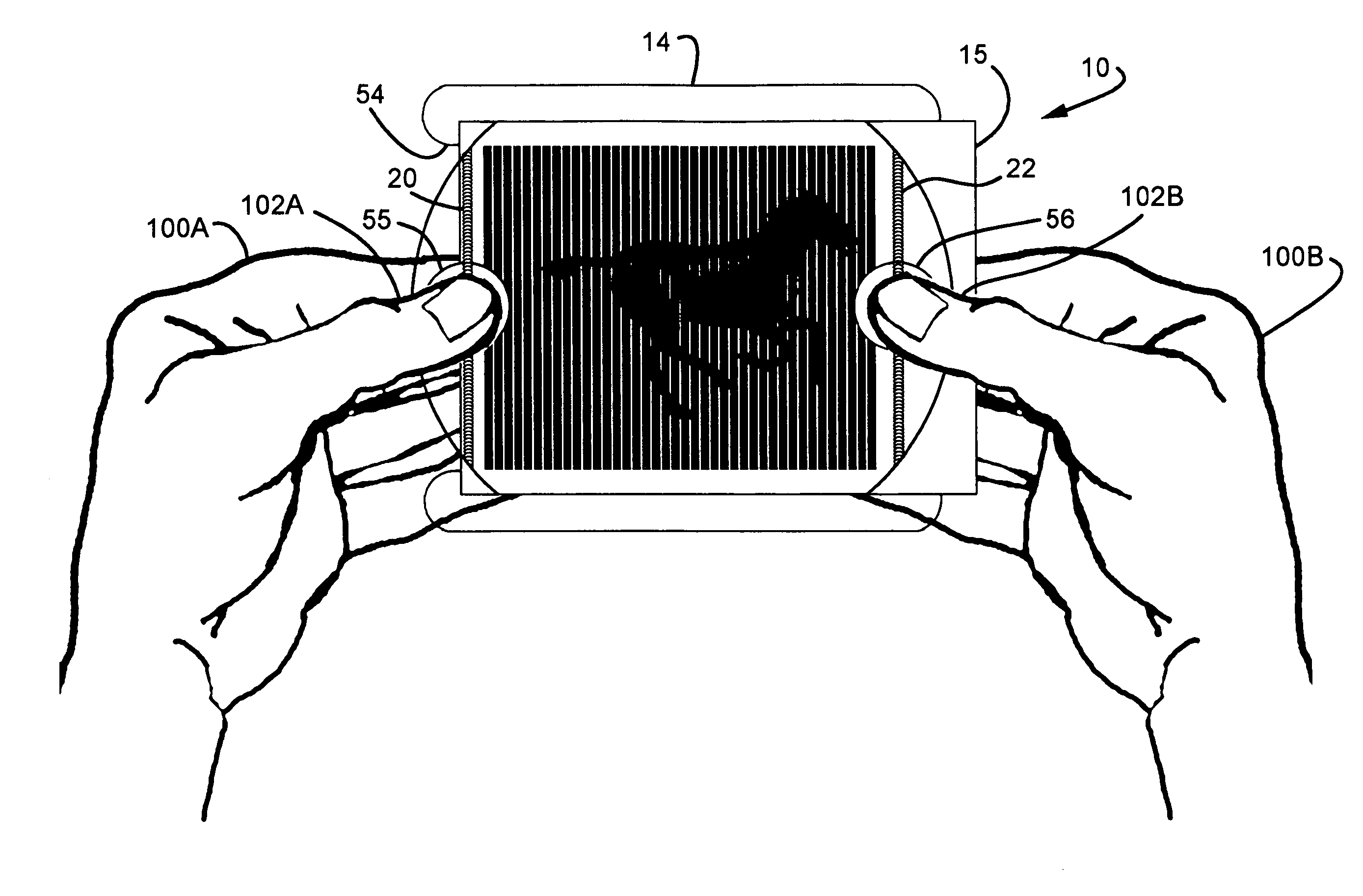
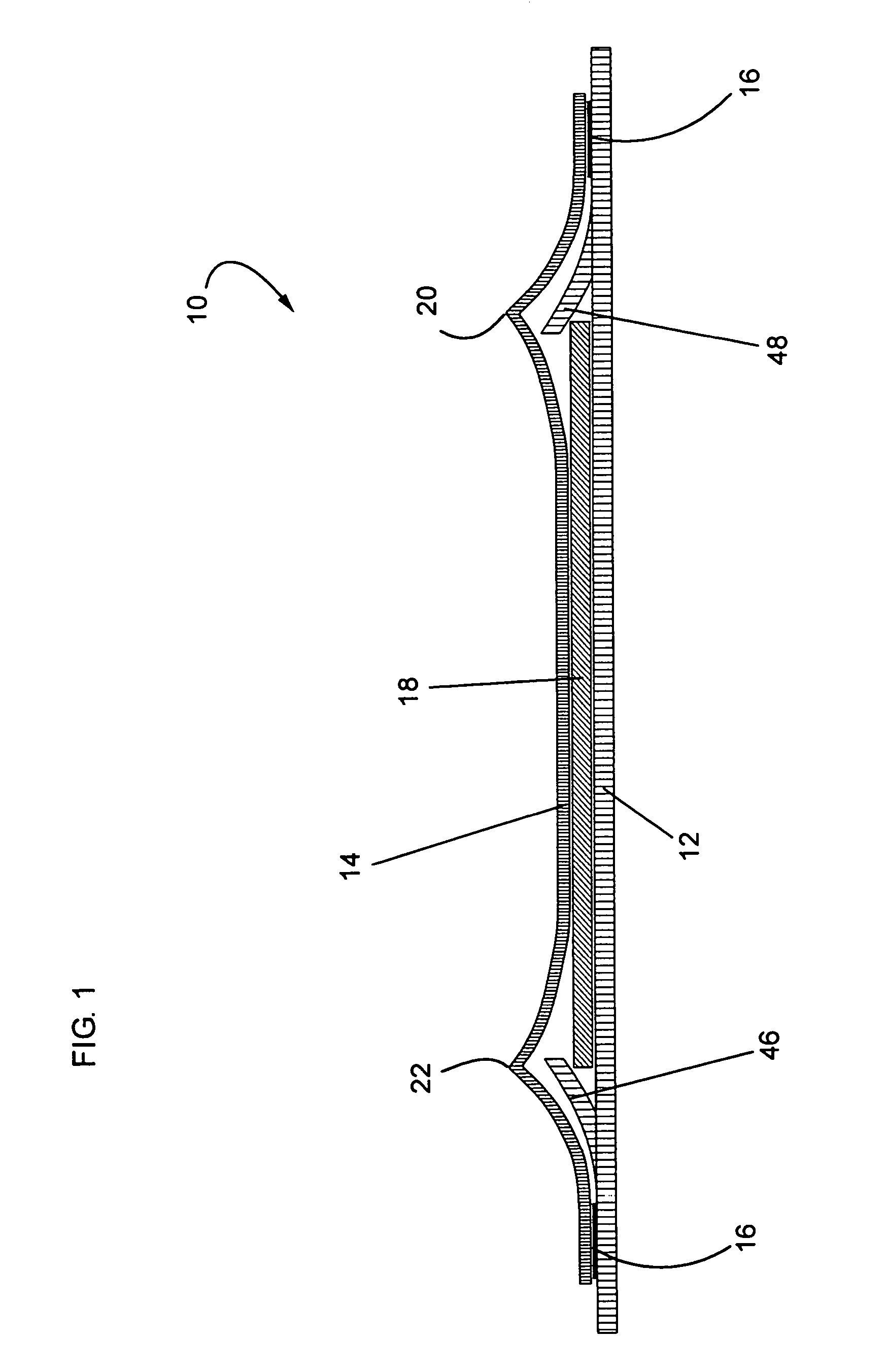
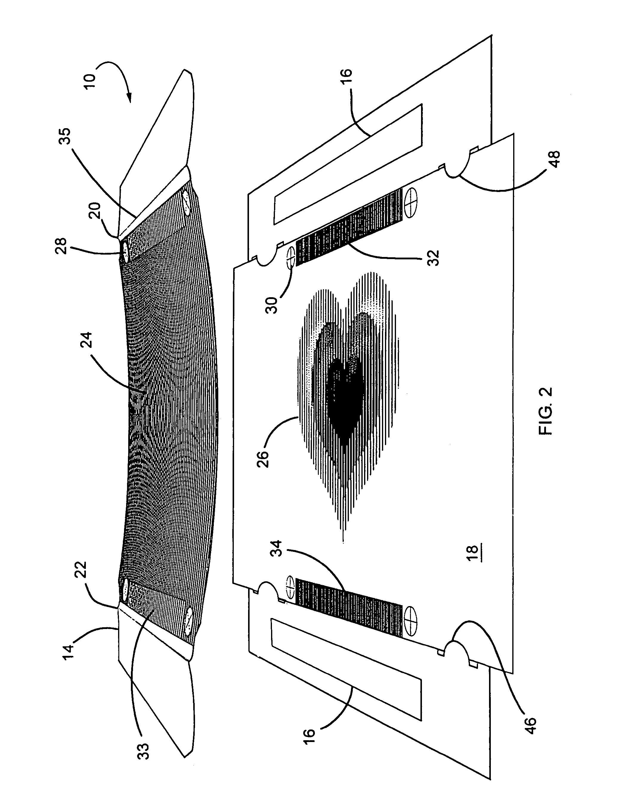
[0035]Looking more particularly to the drawings, an exemplary embodiment of a moveable animated display device according to the present invention is shown in simplified form in FIG. 1 where the device is indicated generally at 10. There, the moveable animated display device 10 is founded on what may be termed a pressure plate carrier 12. A pressure plate 14 has first and second end portions fixed to the pressure plate carrier 12 by any appropriate means, such as adhesive strips 16 as shown in FIG. 1, mechanical fasteners, frictional retention, or any other effective arrangement. A relatively moveable animation l...


PUM


Abstract

A moveable animated display device for displaying a plurality of images with a pressure plate carrier, a pressure plate retained in relation to the pressure plate carrier, a plurality of coded images, a plurality of shutter elements slidably retained in relation to the plurality of coded images, and at least one biasing formation, such as a crease, in the pressure plate for inducing a biasing of the pressure plate toward the pressure plate carrier. The display device can have the pressure plate slidably retained relative to the pressure plate carrier, and the biasing formation can be parallel or orthogonal to a path of travel of the pressure plate in relation to the pressure plate carrier. The display device can comprise a card wherein a pivoting of a cover member relative to a base member induces animation as an animation layer slides in relation to the pressure plate.

Description

[0001]This application claims benefit of application Ser. No. 60 / 534,894 filed on Jan. 8, 2004.FIELD OF THE INVENTION[0002]The present invention relates generally to display devices. More particularly, disclosed herein is a moveable animated display device for displaying a plurality of images in response to a movement of a shutter member relative to an image member.BACKGROUND OF THE INVENTION[0003]Devices permitting the sequential display of a plurality of coded images by relative movement of an image member relative to a shutter member have been known for many years. The image member has a plurality of interposed coded images disposed thereon while the shutter member has a plurality of shutter elements disposed thereon that are separated by a plurality of viewing elements. The shutter elements perform the dual functions of selectively blocking from view all but one of the interposed coded images while bridging the gaps between the coded strips that form what can be termed an active...

Claims


Application Information

Patent Timeline
Patent Type & Authority Patents(United States)
IPC IPC(8): G06T15/00A47F11/06B44F1/00G06K9/62G09F11/00G09F19/08G09F19/12
CPCG09F11/00
Inventor SEDER, RUFUS BUTLER
Owner SEDER RUFUS BUTLER
Why Eureka
Try Eureka