
Virtual private networks

Inactive Publication Date: 2006-12-19
RPX CLEARINGHOUSE
View PDF19 Cites 49 Cited by
  • Summary
  • Abstract
  • Description
  • Claims
  • Application Information

AI Technical Summary

Benefits of technology

[0007]Advantages of the present invention include reducing signaling overhead, eliminating MAC address management on core nodes, decoupling the core L2VPN solution from the distribution model, decoupling the VPN constructs with the VPLS constructs (membership), supporting broadcast domains between all types of PE, allowing PE—PE communication for all types of PE, providing for scaling the number of customer attached PE-ports without impacting the core network (management), working with or without MPLS on the decoupled domain, allowing addition / deletion / modification of PE-Edge without involving configuration on both PE-Edge and PE-Core, and accommodating both Martini and MPLS-in-IP encapsulations.
[0011]Advantages of the present invention include reducing signaling overhead, eliminating MAC address management on core nodes, decoupling the core L2VPN solution from the distribution model, decoupling the VPN constructs with the VPLS (membership), supporting broadcast domains between all types of PE, allowing PE—PE communication for all types of PE, providing for scaling the number of customer attached PE-ports without impacting the core network (management), working with or without MPLS on the decoupled domain, allowing addition / deletion / modification of PE-Edge without involving configuration on both PE-Edge and PE-Core, and accommodating both Martini and MPLS-in-IP encapsulations.

Problems solved by technology

While such arrangement works fine for a small sized VPLS service, such arrangement potentially creates scalability across signaling and data path, flexibility and maintenance issues.
Other issues include limiting of service disruptions due to invalid / corrupt MAC addresses and easing the provisioning and troubleshooting.

Method used


Image

  • Virtual private networks
  • Virtual private networks
  • Virtual private networks

Examples


Embodiment Construction

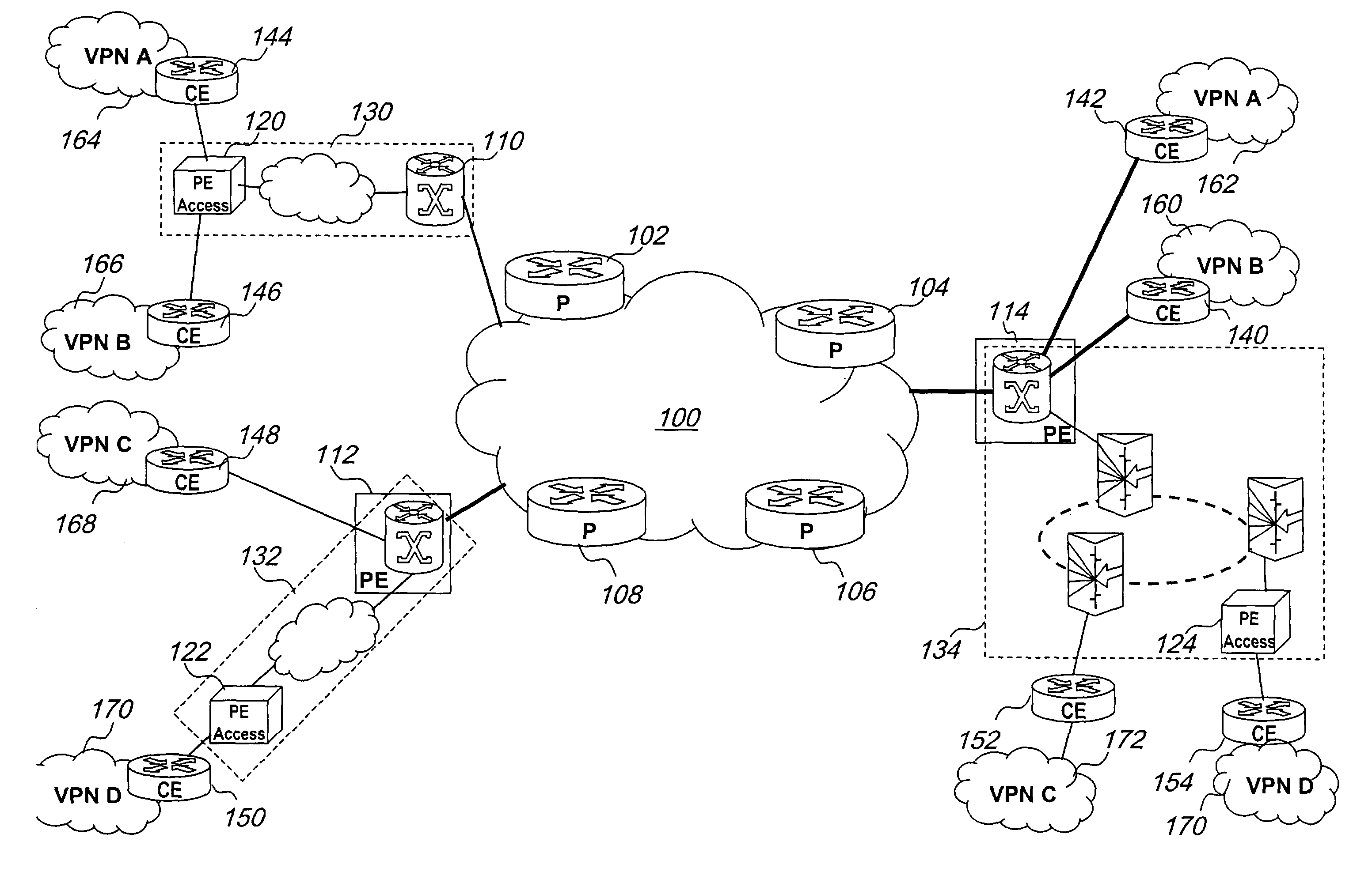
[0016]Referring to FIG. 1 there is illustrated, a logical provider edge in accordance with an embodiment of the present invention. The logical provider edge (LPE) provides a way to organize network components in a hierarchy in order to deliver virtual private LAN segment (VPLS) service. A VPLS is a type of virtual private network in which packets forwarded between VPN sites are Ethernet packets. VPLS service is also known as transparent LAN service (TLS). The logical provider edge 10 includes provider edge device functions 12 and provider edge (PE) core device functions 14 interconnected by a layer 2 (L2) network 16 for providing services at a link 18. The provider edge (PE) edge device functions include:[0017]Configuring Optical Ethernet layer 2 Virtual Private Network (OE L2 VPN) service;[0018]Service labeling;[0019]Ingress traffic management;[0020]Local-core VPN information exchange protocol

[0021]The provider edge (PE) device functions include:[0022]auto-discovery technology[0023...


PUM


Abstract

A network can be organized for providing virtual private network services to customers into two regions. A network core for providing layer 2 transport and an associated number of logical provider edges. Each logical provider edge is partitioned into first and second portions. The first portion provides virtual private network services to customers. The second portion works with the core network to communicate with any other logical provider edge within the network. The first portion designated as the PE-Edge includes a group of functions such as a function for configuring optical Ethernet layer 2 virtual private network service, a function for service labeling, a function for ingress traffic management, and a function for information exchange between local VPN and core VPN. The second portion designated as PE-Core includes a group of functions such as a function for distributing service labels, a function for distributing information on transport tunnels, a function for information exchange between local and core VPN. Within the logical provider edge or Logical PE, the PE-Edge and PE-Core communicate via a layer 2 network.

Description

FIELD OF THE INVENTION[0001]The present invention relates to virtual private networks, and is particularly concerned with layer 2 Ethernet IP / MPLS based virtual private networks.BACKGROUND OF THE INVENTION[0002]Ethernet has emerged as the technology of choice for local area networks (LAN). With speeds of 10 Mbps, 100 Mbps, 1 Gbps and soon 10 Gbps, Ethernet capacity has grown to meet the need for increased network capacities. Price, performance and simplicity have been the network values that Ethernet technology has offered. These have also resulted in the conception of Optical Ethernet networks where optical wavelengths are used as a backbone to carry encapsulated Ethernet packets. This marries the ubiquitous Ethernet with the enormous bandwidth of optical networks. Despite the inherent elegance of this conceptual network, actual implementation of such networks must devise physical and or logical arrangements to insure optimal performance, scalability, and operability.[0003]Traditio...

Claims


Application Information

Patent Timeline
IPC IPC(8): G06F15/173G01R31/08H04L12/66H04L12/46H04L12/56
CPCH04L12/4675H04L45/00H04L45/50Y02B60/44Y02D30/00
Inventor OULD BRAHIM, HAMID H.MOHAN, DINESHRADOACA, VASILECHEN, MICHAEL
Owner RPX CLEARINGHOUSE
Features
  • Generate Ideas
  • Intellectual Property
  • Life Sciences
  • Materials
  • Tech Scout
  • Unparalleled Data Quality
  • Higher Quality Content
  • 60% Fewer Hallucinations
Learn More