
Method for signalling resources to a radio station and radio station therefor

Active Publication Date: 2011-02-17
KONINKLIJKE PHILIPS ELECTRONICS NV
View PDF10 Cites 3 Cited by
  • Summary
  • Abstract
  • Description
  • Claims
  • Application Information

AI Technical Summary

Benefits of technology

[0007]It is another object of the invention to propose a method for signaling of allocation of resources reducing the interference and the overhead.
[0008]Another more specific object of one of the embodiments of the present invention is to reduce the signalling overhead for MU-MIMO systems.

Problems solved by technology

However, for several types of transmission modes, like a Multi User Multiple Input Multiple Output (MU-MIMO) transmission mode for example, where data transmissions to a set of UEs take place in the same (or at least overlapping) time-frequency resources, the amount of overhead arising from the control signalling may therefore become large.

Method used


Image

  • Method for signalling resources to a radio station and radio station therefor
  • Method for signalling resources to a radio station and radio station therefor

Examples


Embodiment Construction

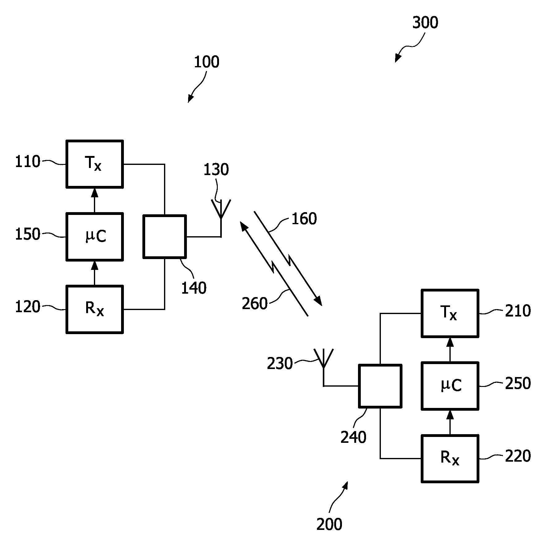
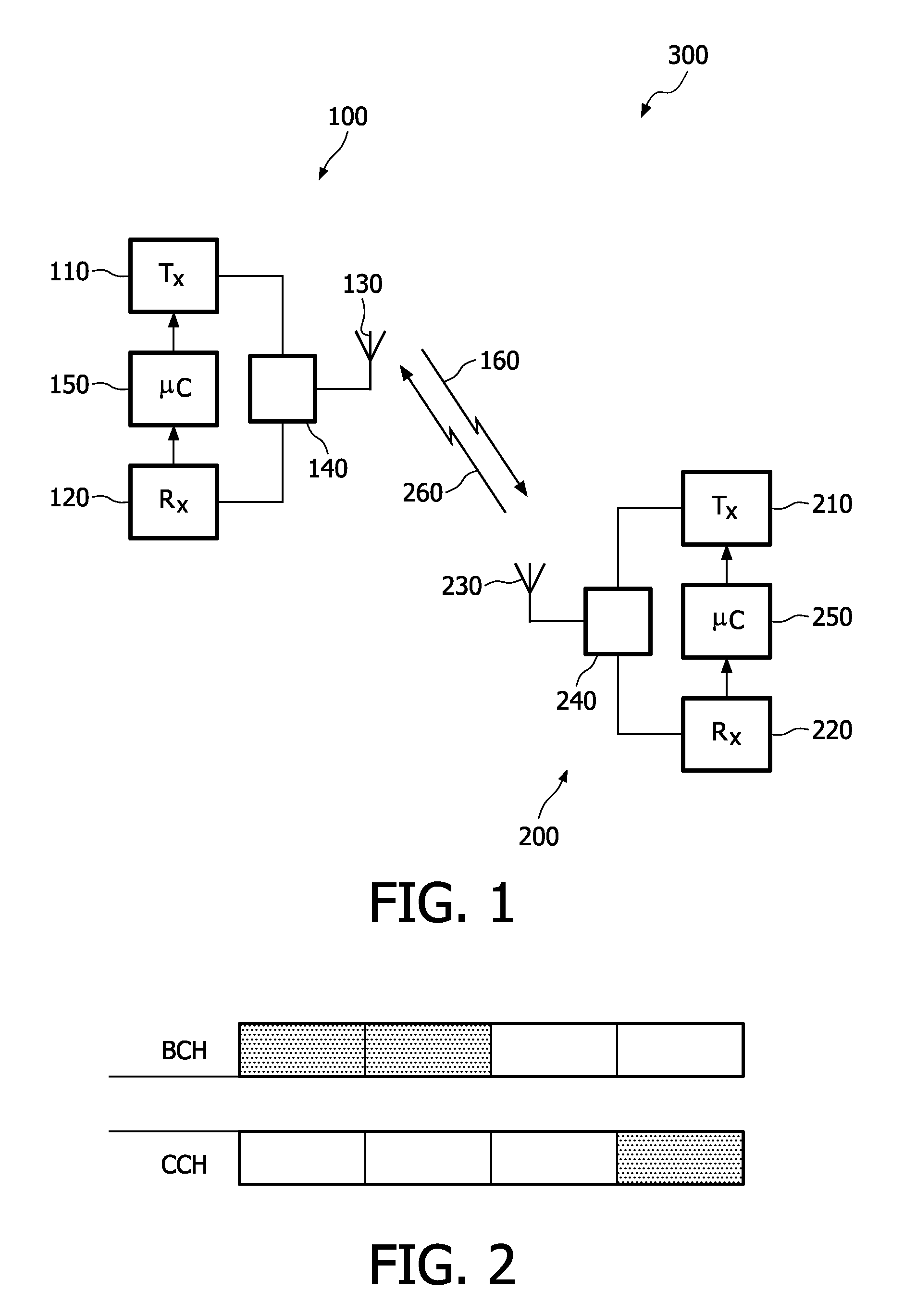
[0019]The present invention relates to a system of communication 300 as depicted on FIG. 1, comprising a primary station 100, like a base station, and at least one secondary station 200 like a mobile station.

[0020]The radio system 300 may comprise a plurality of the primary stations 100 and / or a plurality of secondary stations 200. The primary station 100 comprises a transmitter means 110 and a receiving means 120. An output of the transmitter means 110 and an input of the receiving means 120 are coupled to for example an antenna array 130 comprising a plurality of antennas by a coupling means 140, which may be for example a circulator or a changeover switch. Coupled to the transmitter means 110 and receiving means 120 is a control means 150, which may be for example a processor. The secondary station 200 comprises a transmitter means 210 and a receiving means 220. An output of the transmitter means 210 and an input of the receiving means 220 are coupled for example to an antenna ar...


PUM


Abstract

The present invention relates to a method for signaling a plurality of transmission parameters for a plurality of communications between a primary station and a plurality of respective secondary stations in a multi-user MIMO mode, comprising the steps of (a) signaling the value of at least one first transmission parameter in a multicast message to at least two secondary stations, the value of the first transmission parameter being common to the respective communications corresponding to the at least two secondary stations, and (b) signaling the value of at least one second transmission parameter in a plurality of unicast messages to each secondary stations of the plurality of secondary stations.

Description

FIELD OF THE INVENTION[0001]The present invention relates to a method for signalling resources from a primary station to a plurality of secondary stations. This invention is, for example, relevant for any networks comprising a plurality of radio stations, and more specifically, to a mobile telecommunication network where the secondary stations are for instance able to carry out MIMO transmissions.BACKGROUND OF THE INVENTION[0002]In a network like a mobile telecommunication network, a primary station (like a base station in GSM or an eNode B in UMTS) indicates the transmission resources allocated to the secondary stations (like mobile stations in GSM or User Equipments in UMTS).[0003]For instance, in current versions of the specifications for the UMTS LTE (Long Term Evolution), signalling is provided on a control channel (like the PDCCH, Physical Downlink Control Channel) transmitted from the primary station (eNB) to the secondary station (UE) to indicate the transmission resources u...

Claims


Application Information

Patent Timeline
IPC IPC(8): H04W4/00
CPCH04B7/0452H04L5/0053H04W72/04H04B7/0608H04B7/0617H04L5/023H04B7/0689
Inventor MOULSLEY, TIMOTHY J.BAKER, MATTHEW P.J.
Owner KONINKLIJKE PHILIPS ELECTRONICS NV
Learn More