Method and apparatus for blow molding hollow plastic containers

a technology of hollow plastic containers and molding methods, which is applied in the direction of domestic applications, other domestic articles, domestic articles, etc., can solve the problems of limited push-up heights that can be achieved, and the current wheel-type manufacturing process for containers of this type is not well suited, so as to achieve the effect of improving versatility

Inactive Publication Date: 2006-12-26
GRAHAM PACKAGING PLASTIC PRODS
View PDF36 Cites 167 Cited by
  • Summary
  • Abstract
  • Description
  • Claims
  • Application Information

AI Technical Summary

Benefits of technology

[0001]The present invention is directed to manufacture of hollow plastic containers, and more particularly to a method and apparatus for blow molding hollow plastic containers having improved versatility in terms of the geometries, features and contours of the containers that can be molded.

Problems solved by technology

This limits the push-up height that can be achieved, and requires that the cross section of the container have a positive draft toward the mold parting line.
Current wheel-type manufacturing processes for containers of this type are not well suited for molding the drainback system as one piece integral with the container body and possessing high-definition internal threads.

Method used


Image

  • Method and apparatus for blow molding hollow plastic containers
  • Method and apparatus for blow molding hollow plastic containers
  • Method and apparatus for blow molding hollow plastic containers

Examples


Embodiment Construction

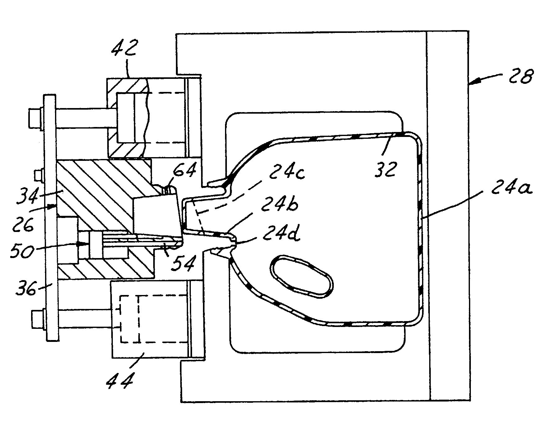
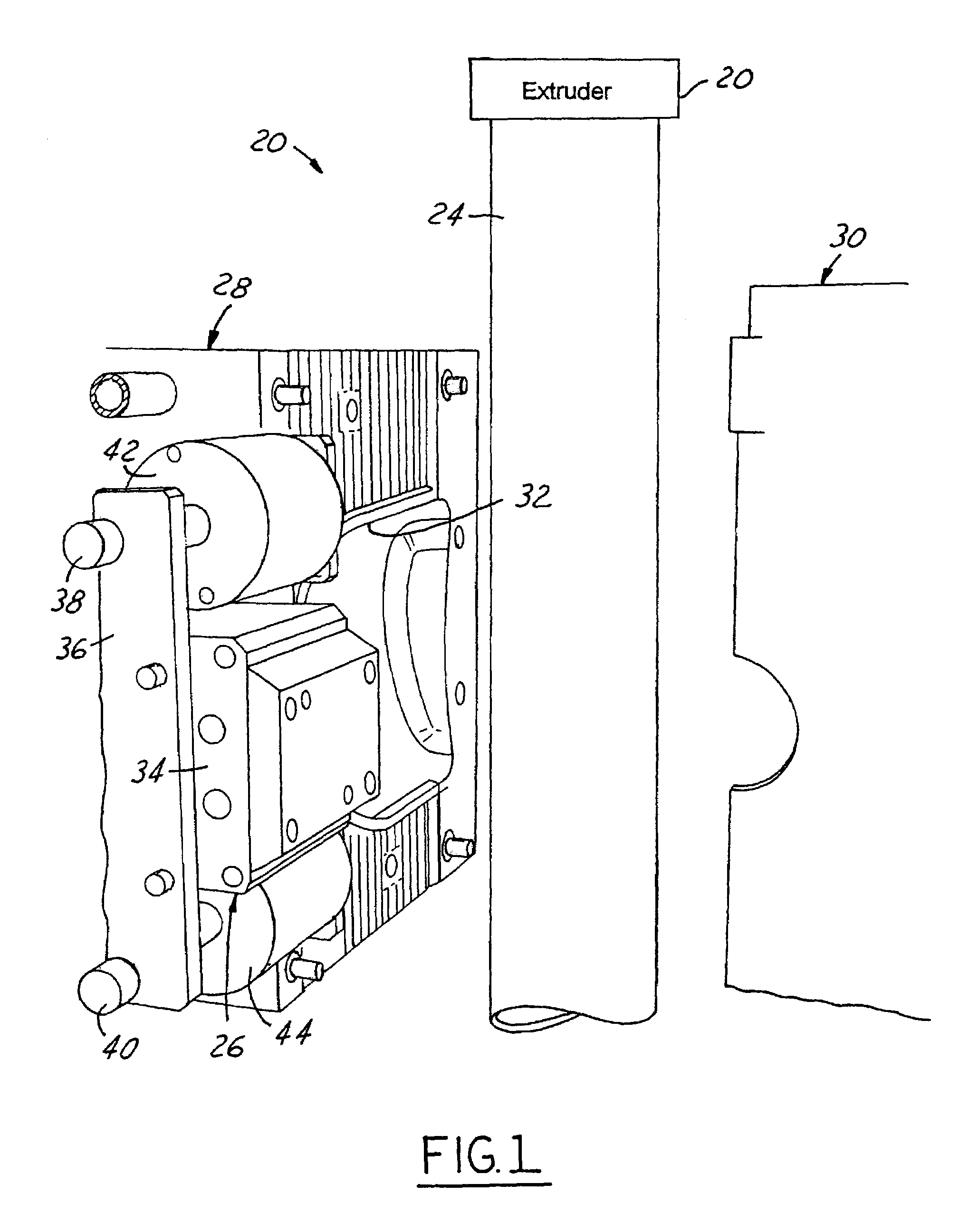
[0020]FIG. 1 illustrates a mold system 20 in accordance with one presently preferred embodiment of the invention as comprising an extruder 22 for extruding a hollow continuous tube 24 of plastic material. As noted above, tube 24 may comprise a monolayer tube, or may comprise a multilayer tube that includes barrier resin layers, adhesive layers, regrind layers, post consumer resin layers, etc. for obtaining desired characteristics in the final container. Tube 24 is typically, but not necessarily, of cylindrical geometry, and is typically, but not necessarily, of uniform wall thickness throughout its length and circumference. A first mold segment 26, a second mold segment 28 and a third mold segment 30 are mounted adjacent to the path of tube 24. At least two of the mold segments—e.g., segments 26 and 30—are movable with respect to each other with respect to mold segment 28 and with respect to the axis of tube 24 between an open position illustrated in FIG. 1 that permits passage of t...


PUM

PropertyMeasurementUnit
movementaaaaaaaaaa
heightaaaaaaaaaa
thicknessaaaaaaaaaa

Abstract

A mold system for blow molding hollow plastic containers includes an extruder for providing a hollow tube of plastic material having a longitudinal axis. Three mold segments include at least two mold segments that are movable against the third mold segment, in directions perpendicular to the tube axis, between a closed position in which the mold segments form a hollow mold cavity in which the tube is captured and an open position spaced from the tube axis. A blow pin is disposed on one of the mold segments to pierce the tube in the closed position of the mold segments. One of the mold segments may be a mold core movably mounted on a second of the mold segments, and cylinders are mounted on the second mold segment for moving the mold core between an extended position and a retracted position with respect to the second mold segment. The blow pin may be movably mounted on the mold core.

Description

[0001]The present invention is directed to manufacture of hollow plastic containers, and more particularly to a method and apparatus for blow molding hollow plastic containers having improved versatility in terms of the geometries, features and contours of the containers that can be molded.BACKGROUND AND SUMMARY OF THE INVENTION[0002]Hollow plastic containers are conventionally fabricated by blowing the containers to the internal confines of a mold cavity formed by a pair of opposed mold segments. The containers must be designed so that they can be removed from the mold after blowing. This requires that any undercuts must be shallow enough to permit the container to be stripped from the mold when the mold is opened. This limits the push-up height that can be achieved, and requires that the cross section of the container have a positive draft toward the mold parting line. A general object of the present invention is to provide a method and apparatus for molding hollow plastic contain...

Claims


Application Information

Patent Timeline
Patent Type & Authority Patents(United States)
IPC IPC(8): B29C49/54B29C49/04B29C49/60
CPCB29C49/4802B29C49/04B29C49/36B29C49/60B29C2049/4807B29L2031/7158
Inventor STRUBLE, DOUGLAS S.SAFIAN, JOHN W.
Owner GRAHAM PACKAGING PLASTIC PRODS
Why Eureka
Try Eureka