
Electrophotographic photoreceptor and image forming apparatus using the photoreceptor

a photoreceptor and photoreceptor technology, applied in the direction of electrographic process, electrographic process using charge pattern, instruments, etc., can solve the problems of low molecular weight charge transport compound, poor mechanical and chemical durability of functionally separated organic photoreceptors, and inability to form films, etc., to achieve good image quality, high durability and stability

Inactive Publication Date: 2006-12-26
RICOH KK
View PDF50 Cites 2 Cited by
  • Summary
  • Abstract
  • Description
  • Claims
  • Application Information

AI Technical Summary

Benefits of technology

[0055]Accordingly, an object of the present invention is to provide an electrophotographic photoreceptor which can produce images having good image qualities and which has high durability and stability.
[0056]Another object of the present invention is to provide an image forming apparatus which can stably produce images having good image qualities without frequently changing its photoreceptor.

Problems solved by technology

However, it is well known that the functionally-separated organic photoreceptors have a drawback of having poor mechanical and chemical durability.
This is because low molecular weight charge transport compounds, which have been typically developed and used as the charge transport material, do not have film forming ability.
However, such a charge transport layer is soft, and therefore has also poor mechanical durability.
In addition, the organic photoreceptors have another drawback such that they easily react with active substances (i.e., corona discharge induced products) such as ozone and nitrogen oxides (NOx), which are generated when charging the photoreceptors in the charging process essential to electrophotography, resulting in deterioration of charge properties of the photoreceptors and occurrence of undesired images such as tailing and blurring.
The abrasion can be improved by these techniques to some extent, however, the latter drawback (i.e., poor resistance to ozone and NOx) cannot be remedied.
Therefore these techniques are not satisfactory.
However, generation of the corona-discharge-induced products cannot be perfectly avoided even when these methods are used.
Therefore, high durability and stability cannot be imparted to an organic photoreceptor only by using these methods.
However, desired durability cannot be imparted to the photoreceptor even when the addition quantity of such an additive is changed.
In addition, there is a possibility that such an additive adversely affects the properties of the photoreceptor such as electric property and the like.

Method used


Image

  • Electrophotographic photoreceptor and image forming apparatus using the photoreceptor
  • Electrophotographic photoreceptor and image forming apparatus using the photoreceptor
  • Electrophotographic photoreceptor and image forming apparatus using the photoreceptor

Examples


example 1

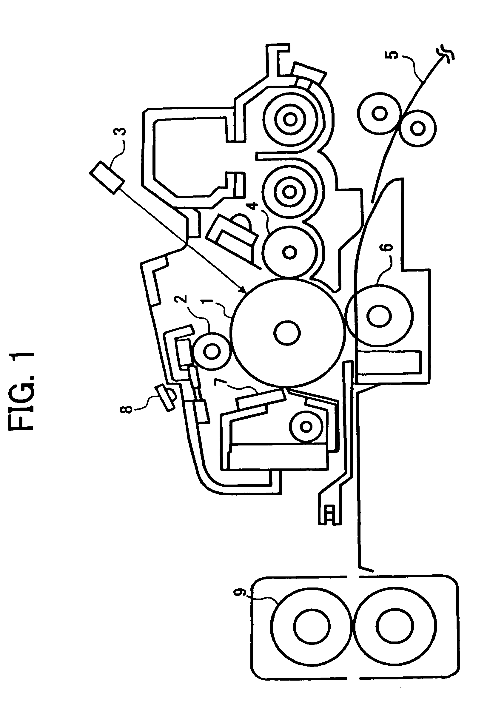
[0261]The photoreceptor 1 was set in the image forming apparatus (modified Imagio MF200) to perform the running test mentioned above. The image forming conditions were as follows:[0262]Charging method: contact charging method using a roller and applying DC voltage[0263]Cleaning element: cleaning blade (as shown in FIG. 1)[0264]Lubricant applying device: not used

[0265]The results are shown in Table 1.

example 2

[0266]The procedure for the running test performed in Example 1 was repeated except that the photoreceptor 1 was replaced with the photoreceptor 2.

[0267]The results are also shown in Table 1.

example 3

[0268]The procedure for the running test performed in Example 1 was repeated except that the photoreceptor 1 was replaced with the photoreceptor 3.

[0269]The results are also shown in Table 1.


PUM

PropertyMeasurementUnit
diameteraaaaaaaaaa
thicknessaaaaaaaaaa
thicknessaaaaaaaaaa

Abstract

An electrophotographic photoreceptor including a photosensitive layer on an electroconductive substrate, wherein nitrate ion is present on the surface of the photosensitive layer in an amount of from 50 to 300 μg per 1 m2 of the surface of the photosensitive layer when the nitrate ion is determined by an ion chromatographic method. Preferably a material having a fluorine atom and a carbon atom or a fatty acid metal salt such as zinc stearate is further present on the surface of the photosensitive layer such that the F / C ratio is from 0.05 to 0.5 or the Zn / C ratio is from 0.001 to 0.1. An image forming apparatus using the photoreceptor is also provided.

Description

[0001]This application is a division of application Ser. No. 10 / 352,075 filed on Jan. 28, 2003, which is a division of application Ser. No. 09 / 796,470 filed on Mar. 2, 2001, now U.S. Pat. No. 6,558,862, which was published in English.BACKGROUND OF THE INVENTION[0002]1. Field of the Invention[0003]The present invention relates to an electrophotographic photoreceptor for use in image forming apparatus such as copiers, facsimile machines, laser printers, and digital plate making machines. In addition, the present invention also relates to an image forming apparatus and process cartridge using the photoreceptor.[0004]2. Discussion of the Background[0005]Electrophotographic image forming methods using a photoreceptor, which are used for copiers, facsimile machines, laser printers, direct digital plate making machines etc., are well known. The image forming methods typically include the following processes:[0006](1) charging an electrophotographic photoreceptor (charging process);[0007](2...

Claims


Application Information

Patent Timeline
Patent Type & Authority Patents(United States)
IPC IPC(8): G03G21/00G03G9/08G03G5/04G03G5/047G03G5/05G03G5/06G03G5/082G03G5/147
CPCG03G5/047G03G5/0503G03G5/0507G03G5/0525G03G5/0539G03G5/0589G03G5/0614G03G5/08285G03G5/147G03G5/14704G03G5/14708G03G5/14726G03G5/14786G03G5/14791G03G5/14795G03G5/06147
Inventor KOJIMA, NARIHITOTAKEICHI, RYUTANAMIKI, AKIYONAGAME, HIROSHISAKON, YOHTA
Owner RICOH KK
Learn More