Distribution cable having overmolded mid-span access location with preferential bending

a technology of distribution cable and access location, which is applied in the direction of optics, fibre mechanical structures, instruments, etc., can solve the problems of affecting the service life of the overmold, so as to prevent damage to the encapsulated optical fiber, reduce the path length difference, and prevent the breakage of the terminated optical fiber

Active Publication Date: 2006-12-26
CORNING OPTICAL COMM LLC
View PDF8 Cites 40 Cited by
  • Summary
  • Abstract
  • Description
  • Claims
  • Application Information

AI Technical Summary

Benefits of technology

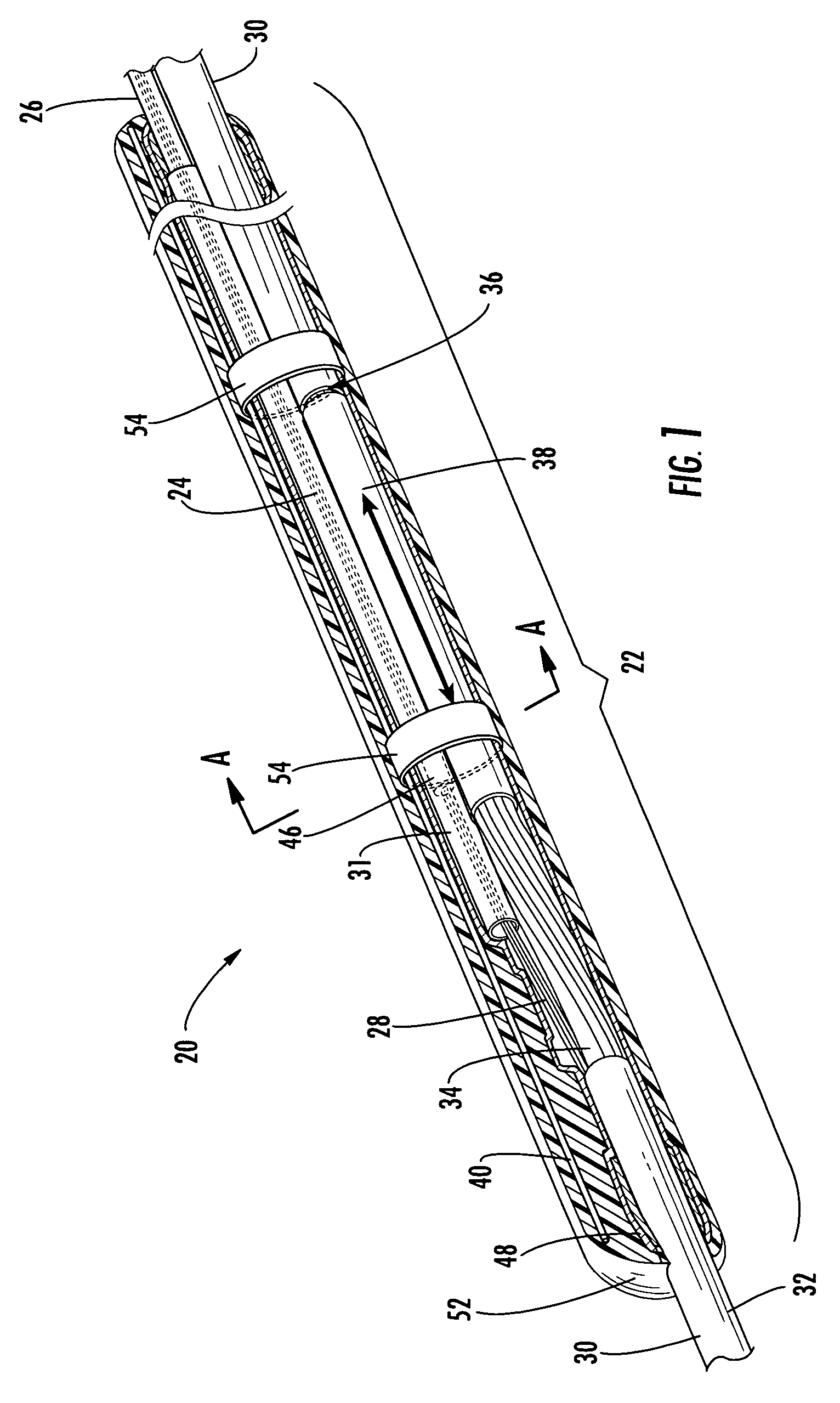
[0010]To achieve the foregoing and other objects, and in accordance with the purposes of the invention as embodied and broadly described herein, the present invention provides various embodiments of a factory-prepared fiber optic distribution cable assembly having at least one predetermined mid-span access location with a preferential bend to reduce the path length differences between the optical fibers terminated from the distribution cable and the optical fibers remaining in the helically wound buffer tubes of the distribution cable, thereby preventing breakage of the terminated optical fibers due to axial tension stresses induced by bending. At each mid-span access location, a plurality of optical fibers are accessed, severed, transitioned and routed separately from the remaining optical fibers of the distribution cable. The terminated optical fibers are spliced or otherwise optically connected to respective optical fibers of a tether cable. The downstream end of the tether cable may terminate in splice-ready optical fibers, connectorized optical fibers, one or more optical connection terminals, a pedestal or any other terminal for connecting optical fibers. As used herein, the terms “tether” and “tether cable” should be understood to include any fiber optic cable, drop cable, branch cable, sub-distribution cable or like conduit for routing and protecting at least one optical fiber.
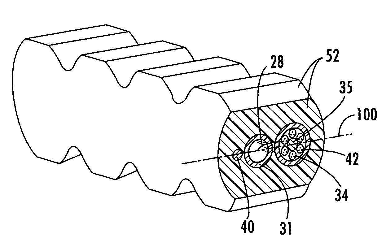
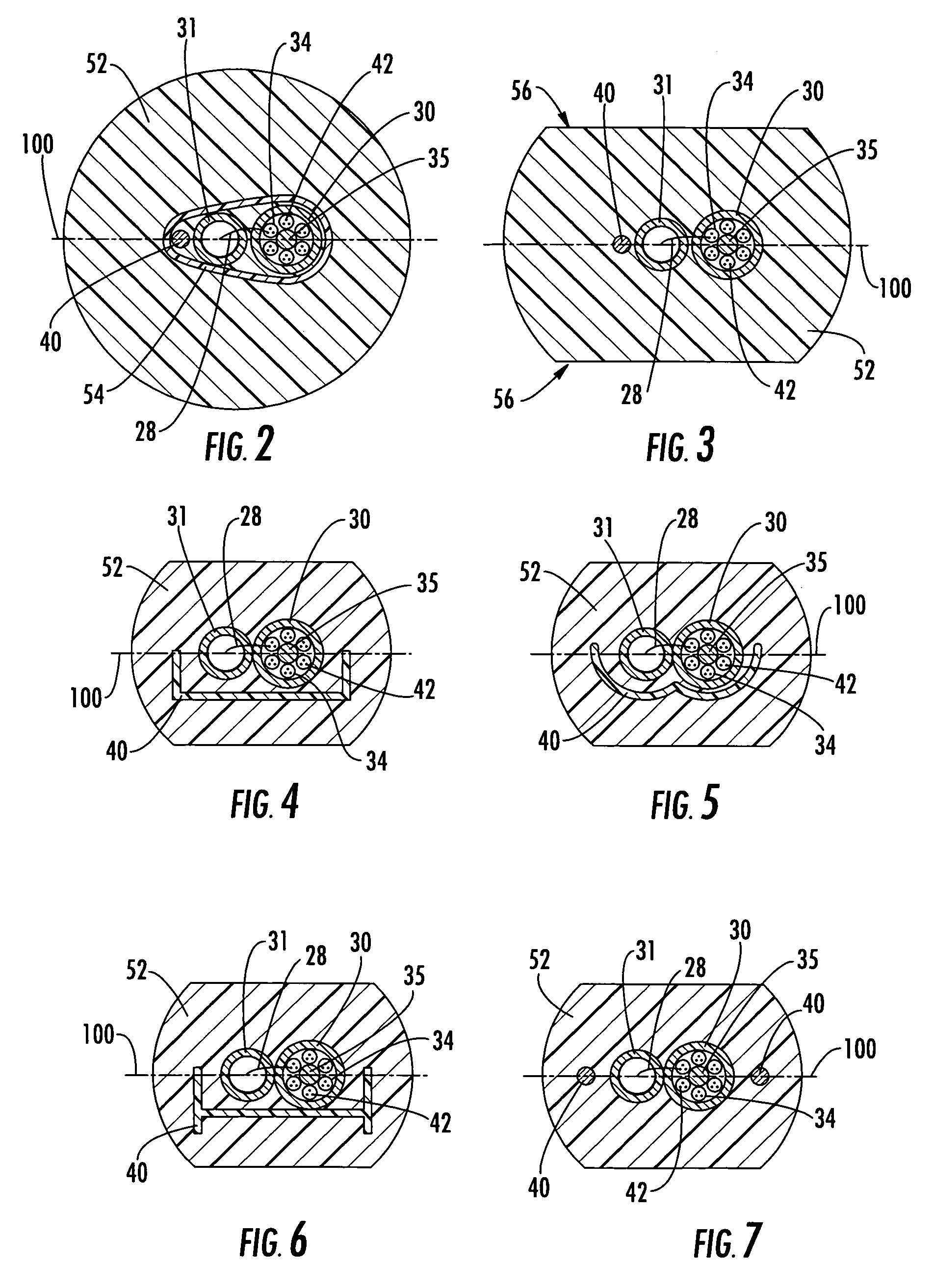
[0011]Each mid-span access location of the distribution cable assembly is provided with a preferential bend such that breakage of terminated optical fibers resulting from axial tension stresses induced by bending is prevented. In particular, the terminated optical fibers are protected during normal handling, cable reeling, un-reeling and installation. The entire distribution cable assembly, including the mid-span access locations and attached tether cables, is suitable for installation through small-diameter conduits or over aerial installation sheave wheels and pulleys as a result of the low-profile design of the mid-span access locations. In several embodiments, a strength member is added to each mid-span access location prior to overmolding in order to provide a preferential bend, thereby preventing damage to the encapsulated optical fibers caused by path length differences that result from bending the mid-span access location. In other embodiments, the mid-span access location is overmolded with a geometrical configuration such that the mid-span access location bends along a preferred axis. In still further embodiments, both a strength member is added to the mid-span access location prior to overmolding, and the mid-span access location is overmolded with a geometrical configuration that promotes bending along a preferred axis.
[0012]In an exemplary embodiment, the present invention provides a factory-prepared fiber optic distribution cable assembly comprising at least one predetermined mid-span access location positioned along the length of the distribution cable, at least one additional strength member axially aligned with the distribution cable, at least one tether attached to the distribution cable at the mid-span access location, and a flexible overmolded body encapsulating the mid-span access location. The alignment of the strength member and the distribution cable creates a preferential bend along a common axis, thereby reducing any path length differences induced by bending and preventing breakage of the optical fibers terminated from the distribution cable.
[0013]In another exemplary embodiment, the present invention provides a factory-prepared fiber optic distribution cable assembly comprising at least one predetermined mid-span access location positioned along the length of the distribution cable, at least one strength member structure having a predetermined shape, at least one tether attached to the distribution cable at the mid-span access location, and a flexible overmolded body encapsulating the mid-span access location and the strength member structure. The addition of the strength member structure creates a preferential bend along a preferred axis, thereby reducing any path length differences induced by bending and preventing breakage of the optical fibers terminated from the distribution cable.
[0014]In yet another exemplary embodiment, the present invention provides a factory-prepared fiber optic distribution cable assembly comprising at least one predetermined mid-span access location positioned along the length of the distribution cable, one or more optical fibers accessed and terminated from the distribution cable at the mid-span access location, a tether cable attached to the distribution cable at the mid-span access location, and a flexible overmolded body encapsulating the mid-span access location and having a geometric configuration such that a preferential bend is created along a common axis, thereby reducing any path length differences induced by bending and preventing breakage of the optical fibers terminated from the distribution cable.
[0015]In yet another exemplary embodiment, the present invention provides a factory-prepared fiber optic distribution cable assembly comprising at least one predetermined mid-span access location positioned along the length of the distribution cable, one or more optical fibers accessed and terminated from the at least one mid-span access location, an additional strength member axially aligned with the distribution cable, a tether cable attached to the distribution cable at the mid-span access location, and a flexible overmolded body encapsulating the mid-span access location and having a geometric configuration such that a preferential bend is created along a common axis, thereby reducing any path length differences induced by bending and preventing breakage of the optical fibers terminated from the distribution cable.

Problems solved by technology

If the bending strain on the optical fibers is great enough, these path length differences may lead to attenuation, or in a worst case, the optical fibers may fail due to excessive axial tension stresses induced by bending.
In addition to axial tension stresses on the optical fibers, tension stresses may also be placed on the overmolded mid-span access location at places where the overmold material is thinnest, leading to the sealing integrity of the overmold possibly being compromised.
If more than one cable (i.e., the distribution cable and the tether cable) is disposed within the mid-span access location, the thickness of the overmold material around all sides of the cables is not uniform, thus resulting in areas having lesser tensile strength.
Obvious drawbacks to a rigid mid-span access location include the inflexibility to installation requirements and the increased diameter of a rigid mid-span access location.
However, the above examples result in a more complex arrangement having a larger cross-sectional area, thus resulting in installation inflexibility.

Method used


Image

  • Distribution cable having overmolded mid-span access location with preferential bending
  • Distribution cable having overmolded mid-span access location with preferential bending
  • Distribution cable having overmolded mid-span access location with preferential bending

Examples


Embodiment Construction

[0027]The present invention will now be described more fully hereinafter with reference to the accompanying drawings in which exemplary embodiments of the invention are shown. However, the present invention may be embodied in many different forms and should not be construed as limited to the particular embodiments set forth herein. These exemplary embodiments are provided so that this disclosure will be both thorough and complete, and will fully convey the scope of the invention to those skilled in the art. Like reference numbers refer to like elements throughout the various drawings.

[0028]The fiber optic distribution cable assembly of the present invention comprises at least one location along the length of the distribution cable, referred to herein as a “mid-span access location,” for providing access to at least one optical fiber terminated from the distribution cable. In preferred embodiments, the distribution cable assembly comprises a plurality of predetermined mid-span access...


PUM


Abstract

A fiber optic distribution cable assembly having at least one factory-prepared mid-span access location for accessing and terminating optical fibers of the distribution cable includes a tether containing at least one optical fiber optically connected to an optical fiber terminated from the distribution cable and an overmolded body encapsulating the distribution cable and a portion of the tether to form the mid-span access location. The mid-span access location is provided with a preferential bend along an axis that is common to the distribution cable and the tether by a strength member positioned within the overmolded body and / or the overmolded body having a geometrical configuration that promotes bending along the common axis. The preferential bend reduces any path length differences between terminated optical fibers routed substantially on the common axis and optical fibers remaining within the distribution cable induced by bending, thereby preventing breakage of the terminated optical fibers.

Description

CROSS REFERENCE TO RELATED APPLICATION[0001]This application is a continuation in part of co-pending U.S. application Ser. No. 10 / 852,427, filed May 24, 2004, entitled Distribution Cable Assembly Having Overmolded Mid-Span Access Location.BACKGROUND OF THE INVENTION[0002]1. Field of the Invention[0003]The present invention relates generally to a fiber optic distribution cable deployed in a fiber optic communications network and, more particularly, to a factory-prepared fiber optic distribution cable assembly having a flexible overmolded mid-span access location with a preferential bend.[0004]2. Description of the Related Art[0005]Optical fiber is increasingly being used for a variety of broadband applications including voice, video and data transmissions. As a result, there is a need for connecting remote locations to a fiber optic distribution cable in order to provide broadband services to an end user, commonly referred to as a subscriber. In this regard, fiber optic networks are ...

Claims


Application Information

Patent Timeline
Patent Type & Authority Patents(United States)
IPC IPC(8): G02B6/44
CPCG02B6/4475
Inventor ELKINS, II, ROBERT B.NIELSEN, LARS K.LUTHER, JAMES P.THEUERKOM, THOMAS
Owner CORNING OPTICAL COMM LLC
Why Eureka
Try Eureka