Method of locating areas in an image such as a photo mask layout that are sensitive to residual processing effects

a technology of residual processing effects and mask layout, which is applied in the field of integrated circuit mask analysis and locating areas in masks, can solve the problems of affecting the projection printing of mask patterns in integrated circuit layout, affecting image quality, and reducing image quality, so as to dramatically reduce the computational complexity of pattern matching and reduce the use of runtime and memory. the effect of reducing the computational complexity

Inactive Publication Date: 2006-12-26
RGT UNIV OF CALIFORNIA
View PDF7 Cites 57 Cited by
  • Summary
  • Abstract
  • Description
  • Claims
  • Application Information

AI Technical Summary

Benefits of technology

[0009]In accordance with the invention, new algorithms have been created to replace the inefficient bitmap-based algorithms in pattern matching. One new algorithm is based on extracting edges from the geometry, pre-integrating the pattern in one dimension, and adding contributions from each pixel wide strip between two edges of each shape overlapping the pattern. Another new algorithm takes the method one step further to the rectangles themselves, pre-integrating the pattern in two dimensions and adding contributions from each rectangle in the input geometry that overlaps the pattern. Performance analysis shows that both algorithms reduce the computational complexity of pattern matching, thus dramatically reducing both runtime and memory usage. The rectangle algorithm is the most efficient for typical layouts, so additional features such as layer Booleans, overlap removal, match filtering, and several speedup methods have been adapted to work with the rectangle data structure. The invention can be extrapolated to triangle primitives for polygons with diagonal lines.
[0011]The rectangle-based algorithm extracts rectangles from the geometry and sorts them by location. Polygons and other non-rectangular shapes are split into a near minimum number of rectangles and snapped to the nearest grid coordinates. The layout is partitioned and polygons are extracted one partition at a time prior to splitting. Each partition is further divided into regions equal in size to the largest pattern used for matching. When the pattern is laid over the geometry, it can thus overlap at most a 2×2 group of regions. Each region is associated with an array containing the indices of each rectangle overlapping that region, and another data structure is built to contain a unique list of the rectangles overlapping any group of 2×2 regions. This final data structure can be used to iterate through all the rectangles overlapping the pattern by looking into the array representing the group of four regions that the pattern overlaps. In this algorithm the pattern is integrated in two dimensions so that the integrated value of a pixel P(x,y) equals the sum of all pixels both above and to the left of the point, including the point itself. The weight of the pattern pixels under a rectangle at (x1,y1), (x2,y2) is PW(r)=P(x1,y1)+P(x2,y2)−P(x1,y2)−P(x2,y1). Using this equation, each rectangle contributes a value of weight(r)*PW(r) to the match factor at that point. For layouts containing diagonal edges, a triangular algorithm can be used with the rectangular algorithm to further improve the speed and accuracy of pattern matching.

Problems solved by technology

At these dimensions, the projection printing of mask patterns in integrated circuit layout can be adversely impacted by small residual aberrations in the lens system.
While the quality metric (Strehl ratio) of today's projection printers is within a few percent of unity, residual aberrations still contribute significant spillover of signals from one mask opening to another.
These spillover effects degrade the image quality with position within the field of the die.
However, the bitmap algorithm is too slow and too data intensive.

Method used


Image

  • Method of locating areas in an image such as a photo mask layout that are sensitive to residual processing effects
  • Method of locating areas in an image such as a photo mask layout that are sensitive to residual processing effects
  • Method of locating areas in an image such as a photo mask layout that are sensitive to residual processing effects

Examples


Embodiment Construction

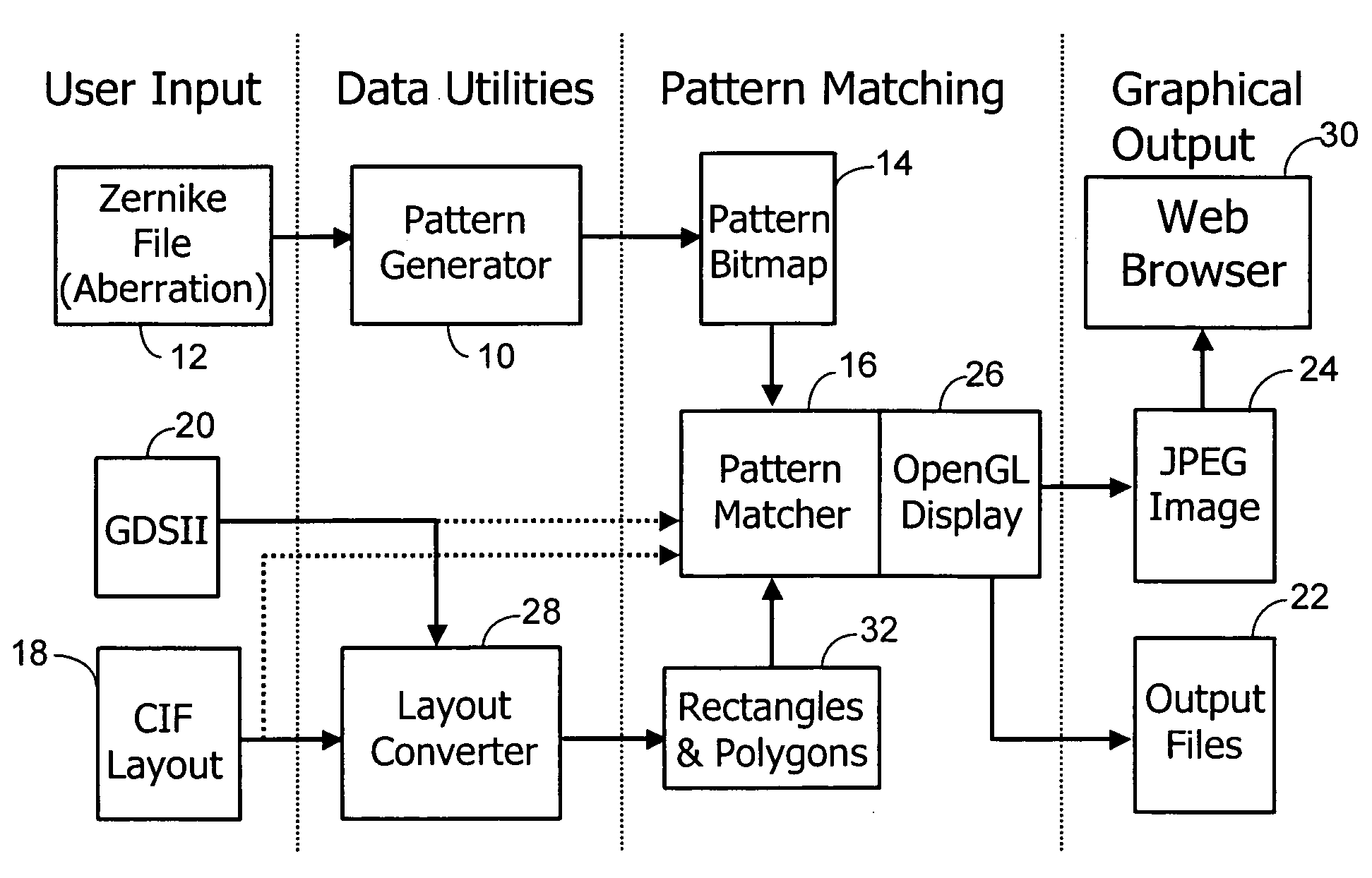
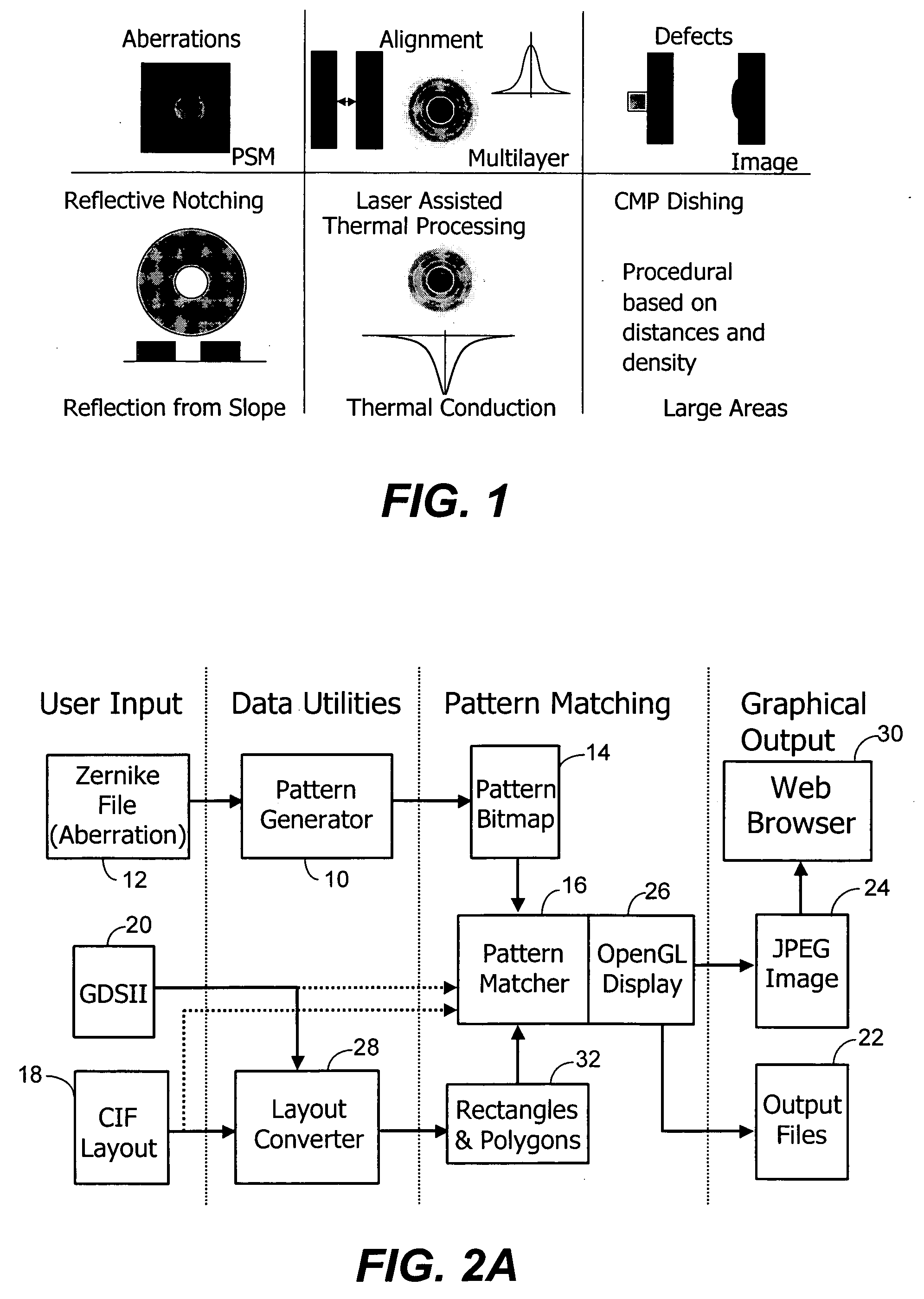
[0037]As the critical dimension in optical lithography continues to shrink and additional phases are added to masks, it is becoming more important to determine where the geometry is affected the most by non-ideal process conditions. If the most problematic shapes can be identified and represented in an unambiguous form, then these test patterns can be used to locate areas in any layout that are the most sensitive to these effects. After the ‘hot spots’ have been found, the designer can go back and alter the geometry to reduce the sensitivity to these effects. Alternatively, these locations can be recorded and later examined after fabrication as a way to narrow down mask inspection regions. Locations of interest can be filtered to edges, line ends, inside corners, and / or outside corners.

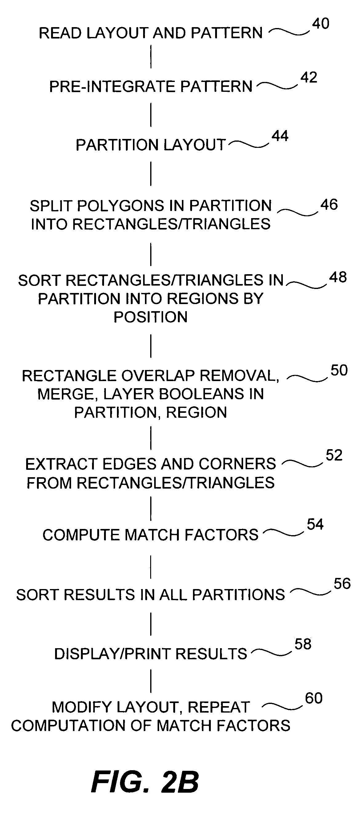
[0038]In accordance with one application of the invention, a software system analyzes a mask layout and searches for locations sensitive to residual processing effects. Pattern matching is used to det...


PUM

PropertyMeasurementUnit
areaaaaaaaaaaa
sizeaaaaaaaaaa
anglesaaaaaaaaaa

Abstract

Images such as mask layouts, signatures, and photographs are compared to identify similarities or dissimilarities in the images. Descriptions of the images use geometric shapes including lines, rectangles, and triangles to facilitate the comparisons and decrease comparison time and decrease stored data describing the shapes. Data for pixels in the shapes are pre-integrated to reduce arithmetic operations in the comparisons.

Description

CROSS-REFERENCES TO RELATED APPLICATIONS[0001]This application claims priority as a continuation-in-part of patent application Ser. No. 10 / 241,242, filed Sep. 10, 2002 now U.S. Pat. No. 7,030,997, which claims the benefit of provisional application Ser. No. 60 / 322,381, filed Sep. 11, 2001, and which are incorporated herein by reference for all purposes.STATEMENT AS TO RIGHTS TO INVENTIONS MADE UNDER FEDERALLY SPONSORED RESEARCH OR DEVELOPMENT[0002]The U.S. Government has rights in the disclosed invention pursuant to DARPA Grant MDA 972-01-1-0021 to the University of California at Berkeley.BACKGROUND OF THE INVENTION[0003]This invention relates generally to imaging lens systems and photo masks for optically defining patterns, and more particularly the invention relates to integrated circuit mask analysis and locating areas in a mask that are sensitive to residual processing effects. The invention has applicability in other image analysis, including signature analysis, for example.[00...

Claims


Application Information

Patent Timeline
Patent Type & Authority Patents(United States)
IPC IPC(8): G06F17/50A61B3/032G03F7/20
CPCA61B3/032A61B3/1015G03F7/706G06T7/0004G06T2207/10061G06T2207/20021G06T2207/20056G06T2207/30141G06T2207/30148
Inventor GENNARI, FRANK E.
Owner RGT UNIV OF CALIFORNIA
Why Eureka
Try Eureka