Attaching structure for a seatbelt apparatus
- Summary
- Abstract
- Description
- Claims
- Application Information
AI Technical Summary
Benefits of technology
Problems solved by technology
Method used
Image

Examples
Embodiment Construction
[0025]The preferred embodiment of the present invention will be explained with reference to the attached drawings.
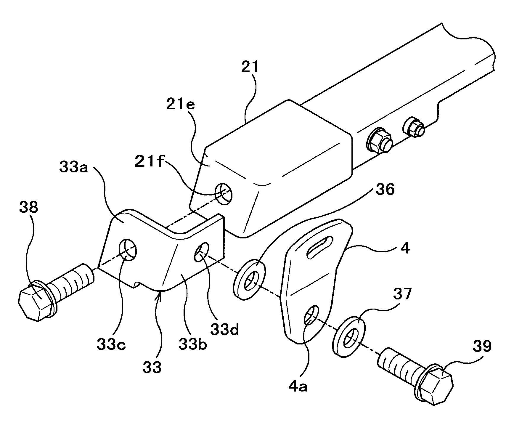
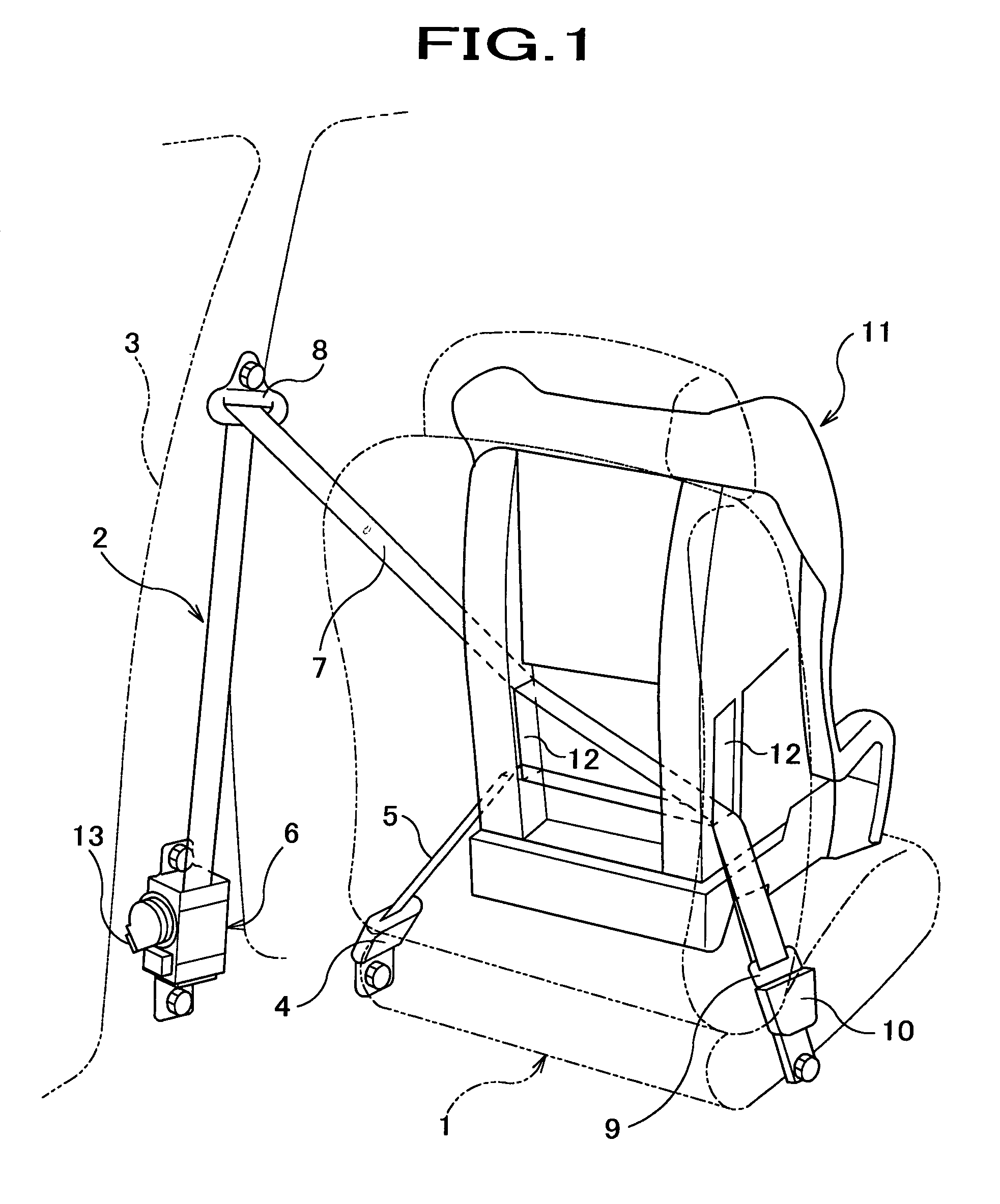
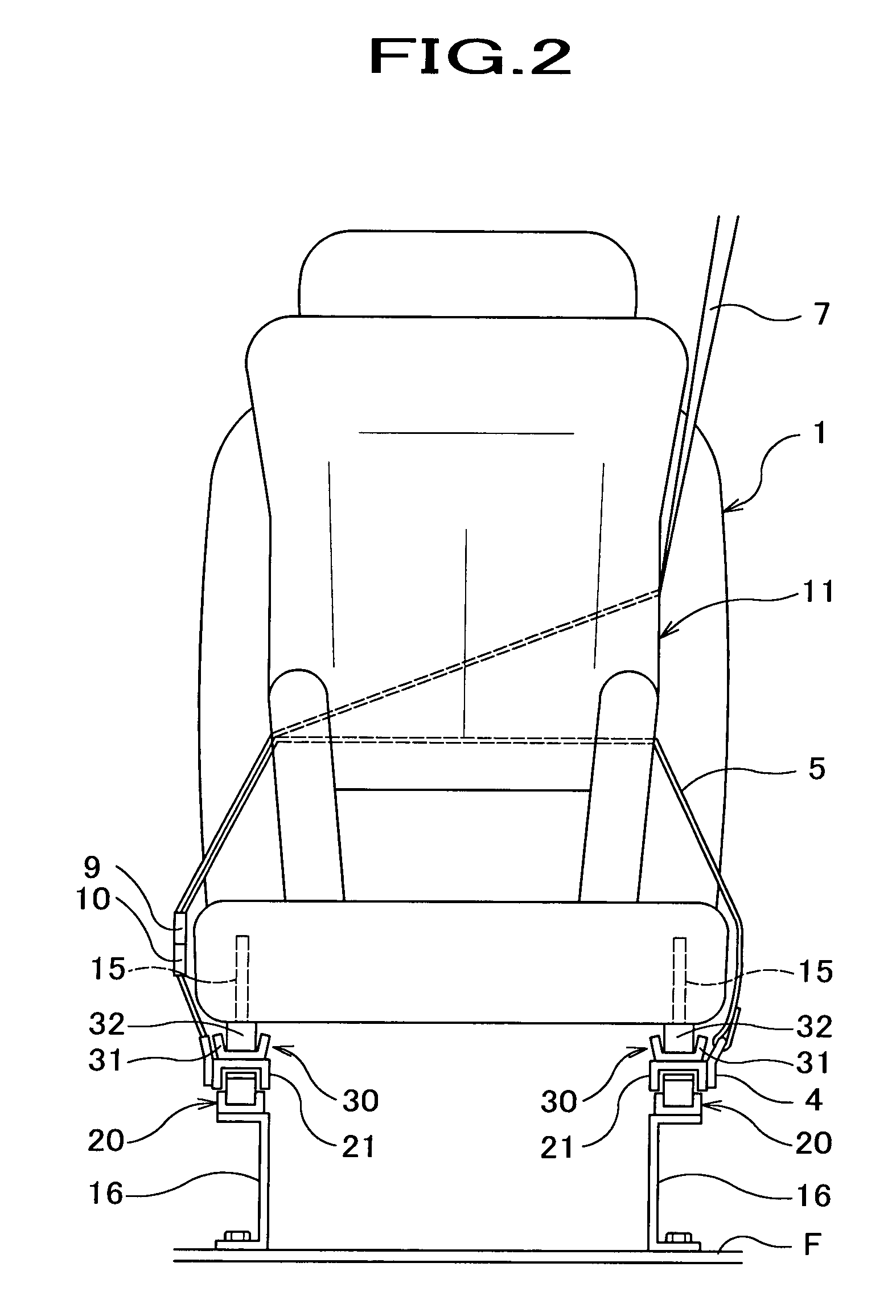
[0026]As shown in FIG. 1, a seatbelt apparatus 2 provided at a seat 1 of a vehicle includes a seatbelt-anchor 4, a lap belt 5, a retractor 6, a shoulder belt 7, a slip guide 8, a tang 9, and a buckle 10.
[0027]In this seatbelt apparatus 2, one end of the lap belt 5 is connected to a seatbelt-anchor 4, which is provided at the outside (door side) in the vicinity of the bottom of the seat 1. The other end of the lap belt 5 is connected to the tang 9, which is engaged to or disengaged from the buckle 10. This buckle 10 is provided at the center side in the vicinity of the bottom of the seat 1.
[0028]To be more precise, the seatbelt-anchor 4 is provided at the door-side near the bottom of the seat 1. The buckle 10 is provided at the cabin-center side near the bottom of the seat 1. One end of the lap belt 5 is connected to the seatbelt-anchor 4, the other end of the lap belt 5 ...
PUM
 Abstract
Description
Claims
Application Information
 - Generate Ideas
- Intellectual Property
- Life Sciences
- Materials
- Tech Scout
- Unparalleled Data Quality
- Higher Quality Content
- 60% Fewer Hallucinations
Browse by: Latest US Patents, China's latest patents, Technical Efficacy Thesaurus, Application Domain, Technology Topic, Popular Technical Reports.
© 2025 PatSnap. All rights reserved.Legal|Privacy policy|Modern Slavery Act Transparency Statement|Sitemap|About US| Contact US: help@patsnap.com