Motion transmitting apparatus

a technology of motion transmission and transmission device, which is applied in the direction of friction gearing, mechanical equipment, belt/chain/gearing, etc., can solve the problems of reducing the efficiency of transmission device, and reducing the cost of transmission device, so as to achieve the effect of less expensive and more versatil

Inactive Publication Date: 2007-01-02
SCHAEFFLER TECH AG & CO KG
View PDF20 Cites 31 Cited by
  • Summary
  • Abstract
  • Description
  • Claims
  • Application Information

AI Technical Summary

Benefits of technology

[0008]An object of the present invention is to provide a novel and improved spindle drive or an analogous drive which is simpler, more versatile and less expensive than heretofore known apparatus of such character.
[0012]Still another object of the invention is to provide a motion transmitting apparatus which can be operated for long periods of time in a simple and reliable manner.
[0014]Another object of the invention is to provide a novel and improved combination of simple parts which can perform the functions of mating internal and external threads.
[0015]An additional object of the invention is to provide a versatile apparatus which can be put to use as a superior (such as longer-lasting) substitute for conventional spindle drives or the like.
[0075]The improved apparatus can be installed in a motor vehicle wherein the prime mover is or can be an internal combustion engine having a rotary output shaft, wherein a second shaft (such as the input shaft of a change-speed transmission) is coaxial with the output shaft, and an engageable / disengageable friction clutch is mounted between the two shafts. The friction clutch is coaxial with the first and second parts of the improved apparatus and can include a component which is movable in the direction of the common axis of the shafts by at least one of the first and second parts to thus change the extent of engagement or disengagement of the friction clutch. The parts of the improved apparatus can be mounted on the second shaft.

Problems solved by technology

It has been found that the ratio of conventional spindle drives, chucks, collets and analogous apparatus (i.e., a ratio which depends upon the lead or pitch of the mating threads and / or upon the root diameter of the external thread) is often too small, even if the means for rotating one of the mating parts includes a rapidly rotating electric motor or an analogous prime mover.
Another drawback of conventional drives or apparatus of the above outlined character is their relatively high cost, not only the initial cost (which includes the cutting or rolling of internal and external threads) but also the maintenance cost.
Thus, in the absence of repeated and intensive lubrication, a conventional spindle drive is bound to require increased quantities of energy due to increased friction between the mating internal and external threads.

Method used


Image

  • Motion transmitting apparatus
  • Motion transmitting apparatus
  • Motion transmitting apparatus

Examples


Embodiment Construction

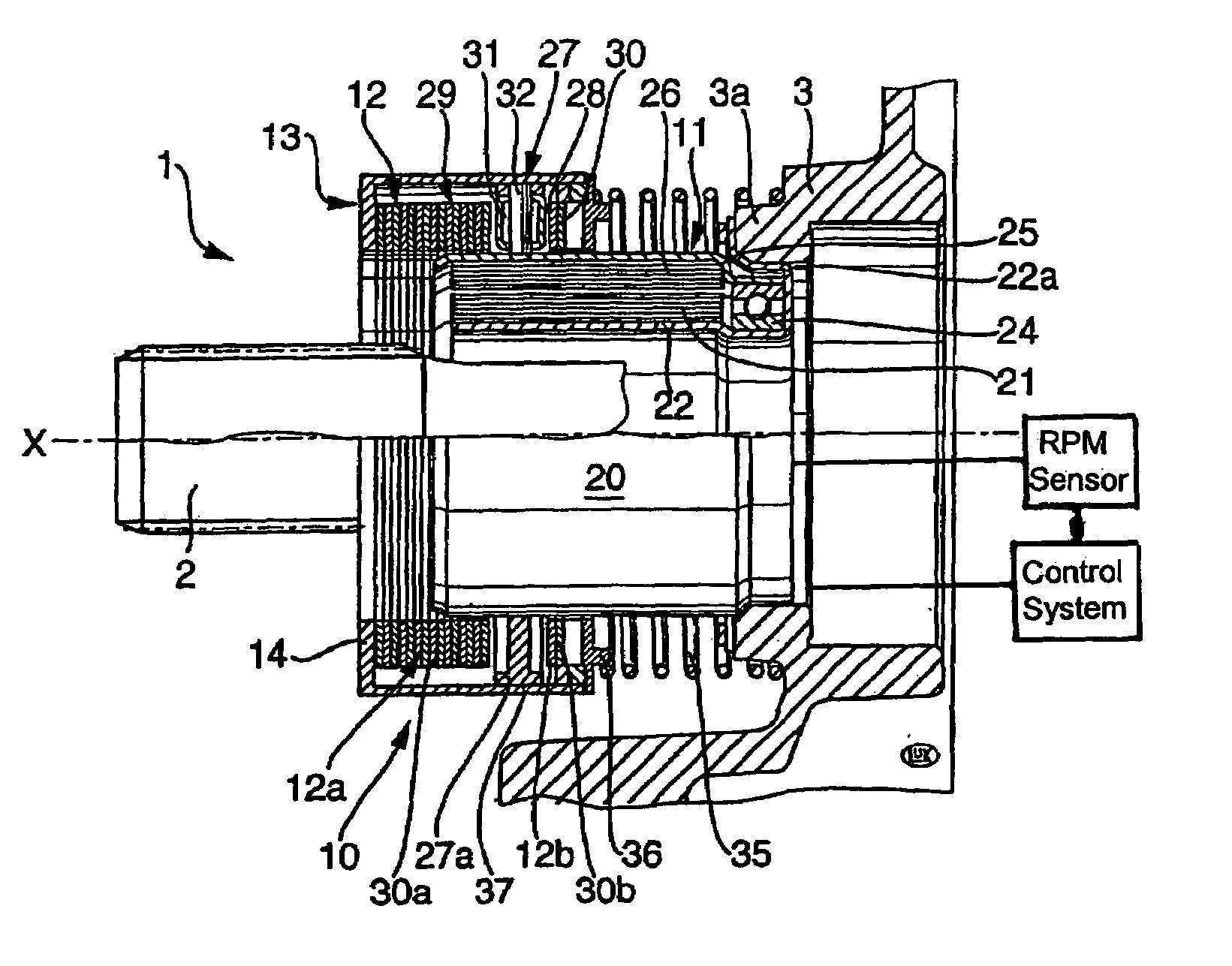
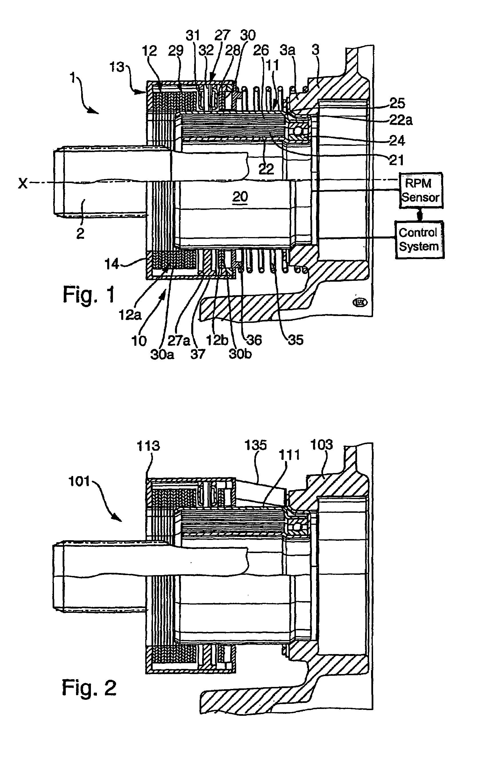
[0112]FIG. 1 shows an apparatus 1 which is designed to effect axial movements of a non-rotatable member or part 13 relative to an axially fixed rotary member or part 11. The part 13 surrounds the part 11 and is movable axially toward and away from a stationary housing or support 3 in response to rotation of the part 11 in one of two directions, i.e., clockwise or counterclockwise. Such axial movability of the part 13 enables the latter to move one or more components (e.g., a release bearing for a friction clutch) between two end positions and to a desired number (including zero number) of intermediate positions. Thus, if a component sharing the axial movements of the part 13 is a clutch release bearing (corresponding to the bearing 711a shown in FIG. 15), such bearing can be moved between a first end position (in which the friction clutch is fully engaged) and a second end position (in which the clutch is fully disengaged) as well as to any desired number of intermediate positions i...


PUM


Abstract

A motion transmitting apparatus wherein an electric motor, an engine or another prime mover rotates an axially fixed first part relative to a coaxial axially movable non-rotatable second part. The structure which serves to move the second part axially in response to clockwise or counterclockwise rotation of the first part includes a follower borne by the first part and a helical spring having end convolutions affixed to the first part. The follower extends between two intermediate convolutions of the helical spring. If the apparatus is utilized in the power train of a motor vehicle, the axially movable part can serve to engage or disengage or change the extent of engagement of the friction clutch between the output element of the engine and the input element of the change-speed transmission.

Description

CROSS-REFERENCE TO RELATED CASES[0001]The present application claims the priorities of German patent application Serial No. 199 32 505.7filed Jul. 12, 1999, of German patent application Serial No. 199 63 238.8 filed Dec. 27, 1999, and German patent application Serial No. 100 15 205.8 filed Mar. 27, 2000, and is a continuation of International patent application Serial No. PCT / DE00 / 02275 filed Jul. 7, 2000.BACKGROUND OF THE INVENTION[0002]The present invention relates to improvements in motion transmitting apparatus in general, and more particularly to improvements in apparatus wherein rotary movements of a first part initiate axial and / or other movements of a second part and / or of the first part.[0003]Motion transmitting apparatus of the type to which the present invention pertains include so-called axial drives or axial transmissions, also called spindle drives, wherein an externally threaded rotary shaft-like member spindle or feed screw mates with an internally threaded part so t...

Claims


Application Information

Patent Timeline
Patent Type & Authority Patents(United States)
IPC IPC(8): F16H25/18F16D23/12F16D28/00B23B31/24F16D21/06F16D25/00F16D27/00F16D27/108F16H19/00F16H25/20F16H25/24
CPCF16D21/06F16D28/00F16H25/2427F16H19/0618F16D27/004F16D2021/0607F16D2021/0646Y10T477/753F16H25/20F16D2023/123Y10T74/18568F16D23/12F16H19/003
Inventor RABER, CHRISTOPH
Owner SCHAEFFLER TECH AG & CO KG
Why Eureka
Try Eureka