Concrete railroad tie with guide plates for the rail base

Active Publication Date: 2007-01-02
PCM RAIL ONE AG
View PDF11 Cites 16 Cited by
  • Summary
  • Abstract
  • Description
  • Claims
  • Application Information

AI Technical Summary

Benefits of technology

[0004]It is therefore an object of the invention to configure a concrete railroad tie of the type named above, so that simpler guiding plates, oc

Problems solved by technology

Due to the omission of the depressions, which previously were basically provided, inserts, which are intended

Method used


Image

  • Concrete railroad tie with guide plates for the rail base
  • Concrete railroad tie with guide plates for the rail base
  • Concrete railroad tie with guide plates for the rail base

Examples


Example

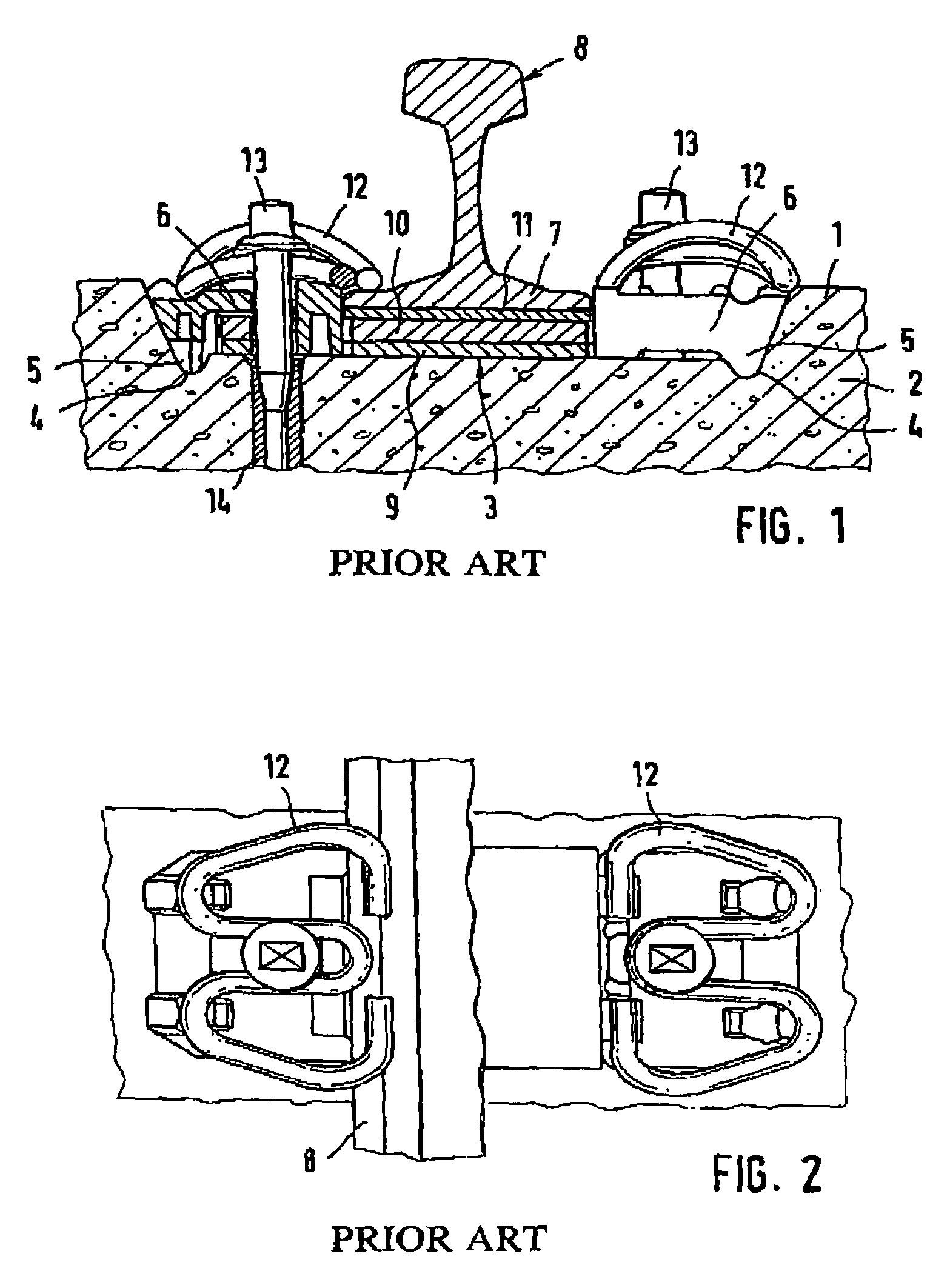
[0020]FIGS. 1 and 2 show a conventional highly elastic rail fastening for solid tracks with a rail support area 3, which is disposed between two raised shoulders 1 of the concrete 2 of the railroad tie and has, aside from a flat middle section, two deep depressions 4, which traverse the railroad tie transversely and accommodate rib-shaped bends 5 of the angle guiding plates 6. These angle-guiding plates 6 are in lateral contact with the base 7 of the rail 8 and are supported at on the other side at the shoulders 1 of the concrete. For the highly elastic mounting of the rail 8, initially an intermediate plate 9 and, on the latter, a base plate 10 are disposed on the rail support area 3. Finally, a further 2 to 12 mm thick intermediate layer 11 is disposed on the intermediate plate 9 underneath the rail base 7. The conventional W-shaped anchor clamps, which can be fastened with the help of railroad tie bolts 13, which in turn engage screw-in dowels 14 in the concrete 2 of the railroad...


PUM


Abstract

A concrete railroad tie, especially a two-block railroad tie, with an elastic rail support for ballast and solid tracks, with guide plates with twisting-prevention devices disposed in the supporting region between the base of the rail and the lateral, raised shoulders of the railroad tie, characterized in that the support area is constructed essentially flat without continuous, deep depressions.

Description

BACKGROUND OF THE INVENTION[0001]The invention relates to a concrete railroad tie, especially to a two-block railroad tie, with an elastic rail support for ballast and solid tracks, with guide plates with twisting-prevention devices disposed in the supporting region between the base of the rail and the lateral, raised shoulders of the railroad tie.[0002]For all conventional, concrete railroad ties, whether monoblock railroad ties or two-block railroad ties for ballast and solid tracks, continuous, relatively deep depressions are produced in the concrete next to the raised shoulders of the railroad tie for accommodating a correspondingly protruding rib of the guide rails, which are constructed as angle guiding plates.[0003]It is one of the disadvantages of this construction that, when producing the concrete railroad ties in the casting molds, inserts with high ribs must be introduced in order to form the depressions. These inserts can only be produced from very high plates, which mus...

Claims


Application Information

Patent Timeline
IPC IPC(8): E01B9/00E01B1/00E01B3/28E01B9/38E01B9/40
CPCE01B3/28E01B1/004E01B9/28
Inventor KOWALSKI, MARTIN
Owner PCM RAIL ONE AG
Why Eureka
Try Eureka