Wind powered pendulating land sail electricity generation system

a pendulating land and electricity generation technology, applied in the direction of electric generator control, machine/engine, greenhouse gas reduction, etc., can solve the problems of wind generators costing more than a million dollars each, fossil fuel electric power plants consuming a large amount of the worlds non-replenishing resources of coal and oil, etc., and achieve the effect of economic manufacture and mark

Inactive Publication Date: 2007-01-02
MOORING JON
View PDF11 Cites 25 Cited by
  • Summary
  • Abstract
  • Description
  • Claims
  • Application Information

AI Technical Summary

Problems solved by technology

The fossil fuel electric power plants continue to consume a large amount of the worlds non-replenishing resources of coal and oil.
Most of these systems are costly when compared to the cost of electricity produced by fossil fuels.
Some of the wind generators can cost more than a million dollars each.

Method used


Image

  • Wind powered pendulating land sail electricity generation system
  • Wind powered pendulating land sail electricity generation system
  • Wind powered pendulating land sail electricity generation system

Examples


Embodiment Construction

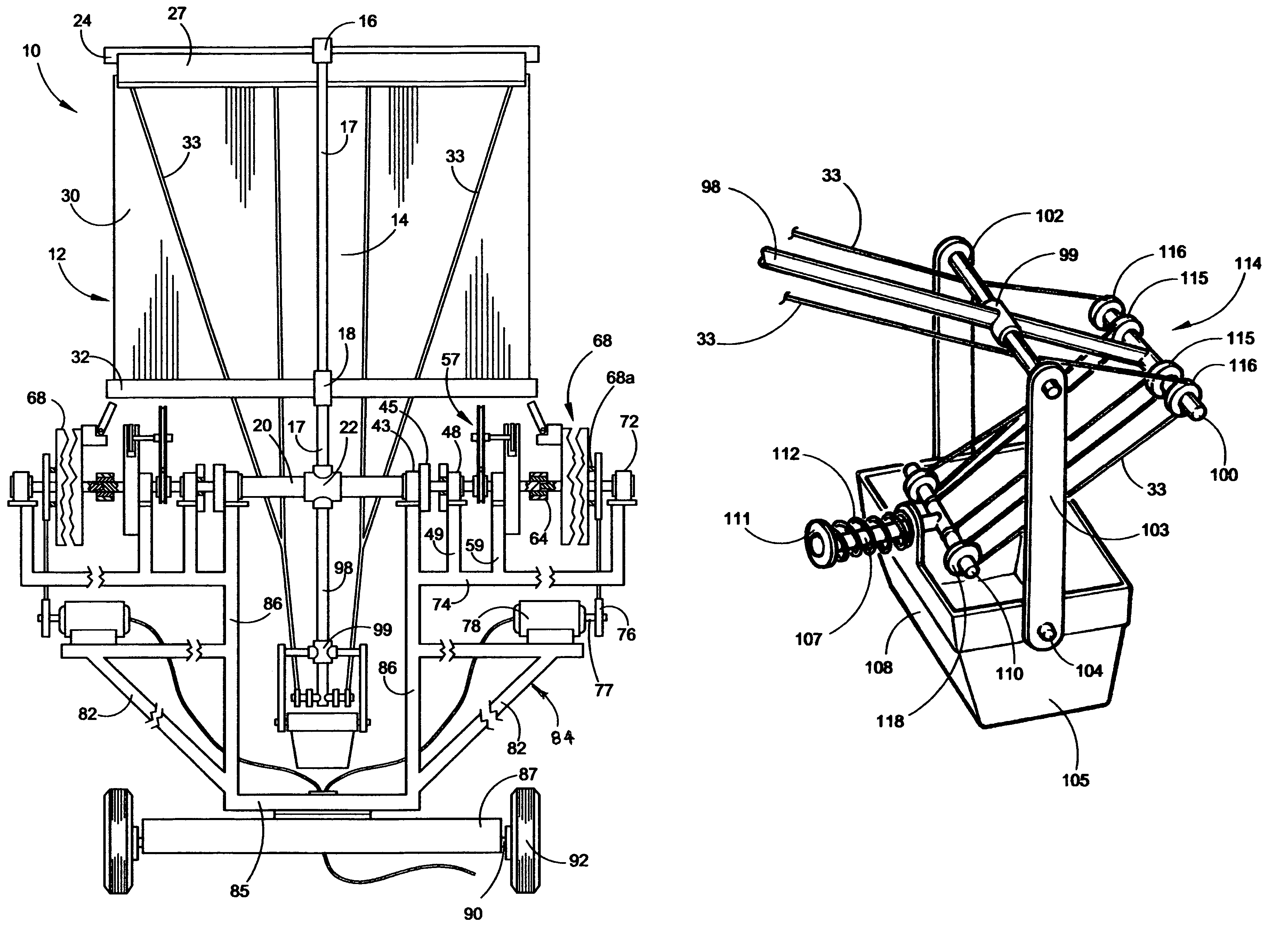
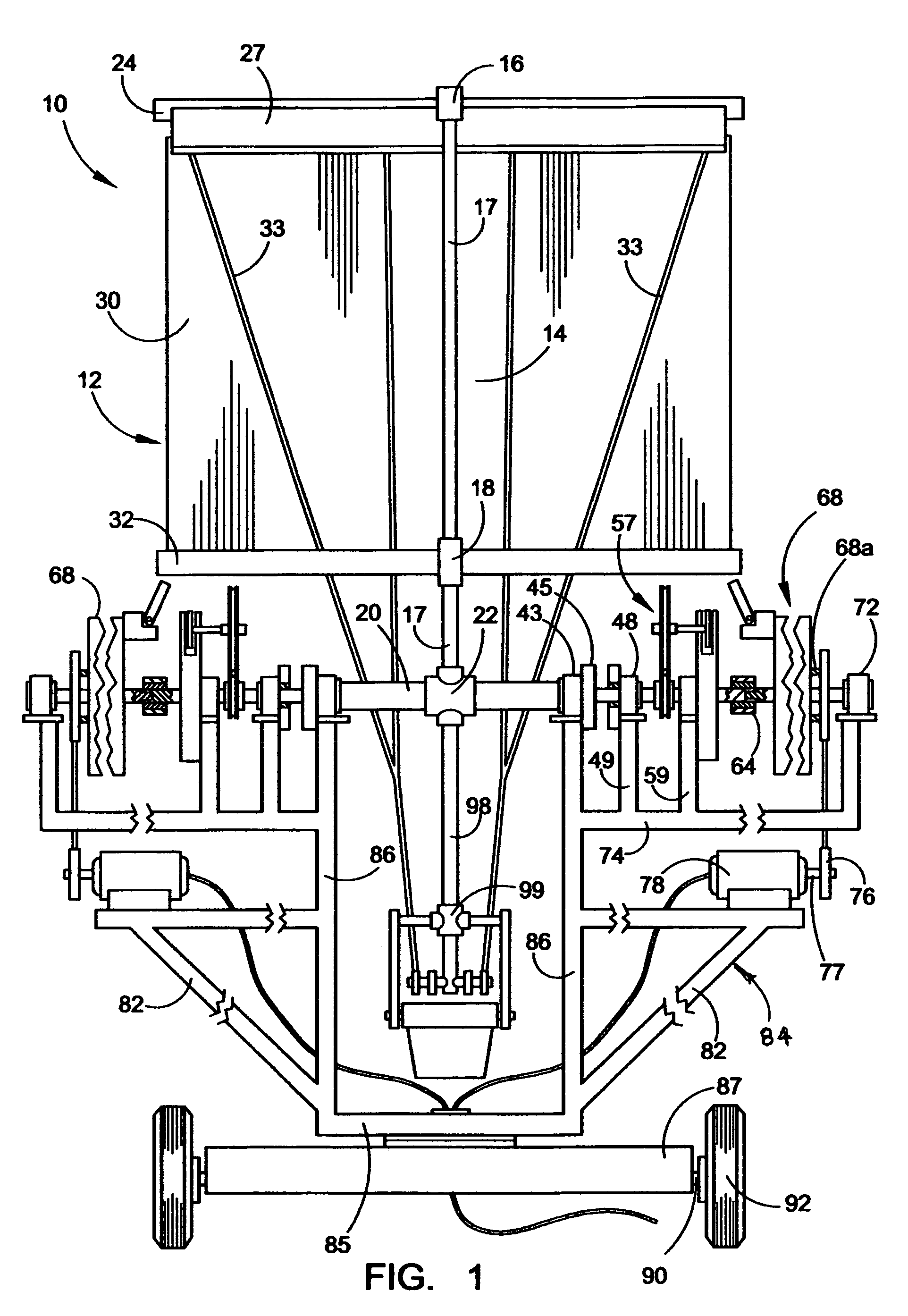
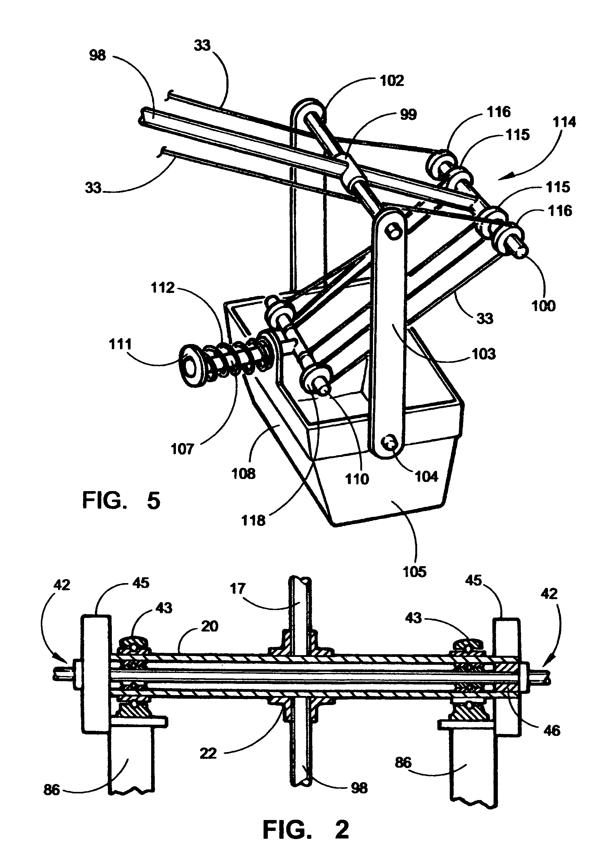
[0024]The wind powered electricity generation system will now be described by referring to FIGS. 1–7 of the drawings. The portable electricity generation station 10 has at least one wind collection sail assembly 12 that is supported by an upper pole assembly unit 14. Additional wind collection said assemblies could be vertically stacked above upper coupling member 16 by extending upper pole member 17 above upper coupling member 16. Upper pole assembly unit 14 has an upper coupling member 16, an upper pole member 17, a lower coupling member 18, and a longitudinally extending Y-axis. The bottom end of upper pole assembly unit 14 is rigidly secured to spring-motor primary winding axle 20 by coupling member 22.

[0025]Referring to FIG. 4, a support member 25 has its front end connected to upper coupling member 16 and its rear end connected to the transversely extending upper support beam 24. An elongated louver flap 27 has its top edge connected to upper support beam 24. A plurality of la...


PUM


Abstract

An electricity generation system having the ability to generate clean electrical power by mechanically capturing the power of the wind. The system utilizes one or more modular wind collecting sail assemblies that are mounted on an upright oriented pole assembly. The bottom end of the pole assembly is rigidly connected to a horizontally oriented elongated spring-motor primary winding axle who's opposite ends are journaled in a base assembly. Each end of the spring-motor primary winding axle is connected to a one way sprague coupling. That coupling is in turn connected to the spring-motor secondary winding axle having one or more spring motors mounted thereon. The inner end of each spring motor metal band is secured to the spring-motor secondary winding axle. When the wind force bends the wind collecting sail assembly from its static upright position, the spring-motor primary winding axle will be rotated causing the spring motors to be wound incrementally each time the wind blows the sail from its static upright position. The spring motor housing is releasably connected to a stationary retention member to prevent rotation of the spring motor housing until the spring motors are wound a sufficient amount. An electricity generator is mounted on the base assembly and there is rotation transmission structure connected to the power generation drive shaft of the electricity generator. When the spring motor assembly has been sufficiently wound, a timing gear assembly releases the motor spring housing assembly allowing it to rotate freely to dissipate stored energy and drive the electricity generator. This cycle is repeated throughout the day to generate electricity when the wind is blowing.

Description

BACKGROUND OF THE INVENTION[0001]The invention relates to an electricity generation system and more specifically to one that is powered by the force of the wind.[0002]The two major forms methods for generating electricity generation utilize water power that turns electricity producing turbines and fossil fuels that power electric power plants. Currently, fewer dams are being built for the purpose of generating hydroelectric power. The fossil fuel electric power plants continue to consume a large amount of the worlds non-replenishing resources of coal and oil. Attempts have been made to use solar energy and wind power to produce electricity from their unlimited source of natural power. Most of these systems are costly when compared to the cost of electricity produced by fossil fuels.[0003]The common wind powered generators have propellers or blades that are rotated by the force of the wind to produce electricity. Some of these wind generators have a tower base 200 feet or higher. The...

Claims


Application Information

Patent Timeline
Patent Type & Authority Patents(United States)
IPC IPC(8): F03D9/00H02P9/04
CPCF03D5/04F03D5/06F03D9/002F03G1/00F03D9/02Y02E10/725F05B2240/94Y02E10/70F03D9/10F03D9/25Y02E10/728F03D15/10F03D13/20Y02E10/72Y02E70/30
Inventor MOORING, JON
Owner MOORING JON
Why Eureka
Try Eureka