Automatic gain control feedback amplifier

a feedback amplifier and gain control technology, applied in gain control, instruments, material analysis, etc., can solve the problems of difficult complicated circuit configuration, and achieve the effect of easy control of the dynamic rang

Active Publication Date: 2007-01-02
ELECTRONICS & TELECOMM RES INST
View PDF5 Cites 10 Cited by
  • Summary
  • Abstract
  • Description
  • Claims
  • Application Information

AI Technical Summary

Benefits of technology

[0014]The present invention provides a feedback amplifier capable of easily controlling its dynamic range without a separate gain control signal generation circuit.

Problems solved by technology

However, due to such a separate gain control signal generation circuit required to obtain a wide dynamic range, an entire circuit configuration is complicated and controlling of the dynamic range is difficult.

Method used


Image

  • Automatic gain control feedback amplifier
  • Automatic gain control feedback amplifier
  • Automatic gain control feedback amplifier

Examples


Embodiment Construction

[0026]Hereinafter, embodiments of the present invention will be described in detail with reference to the appended drawings. Like reference numbers refer to like components throughout the drawings.

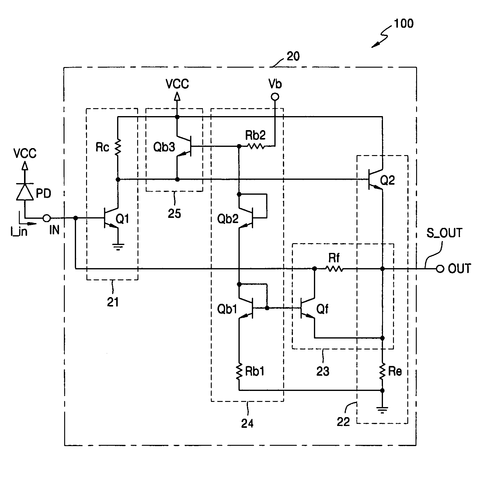
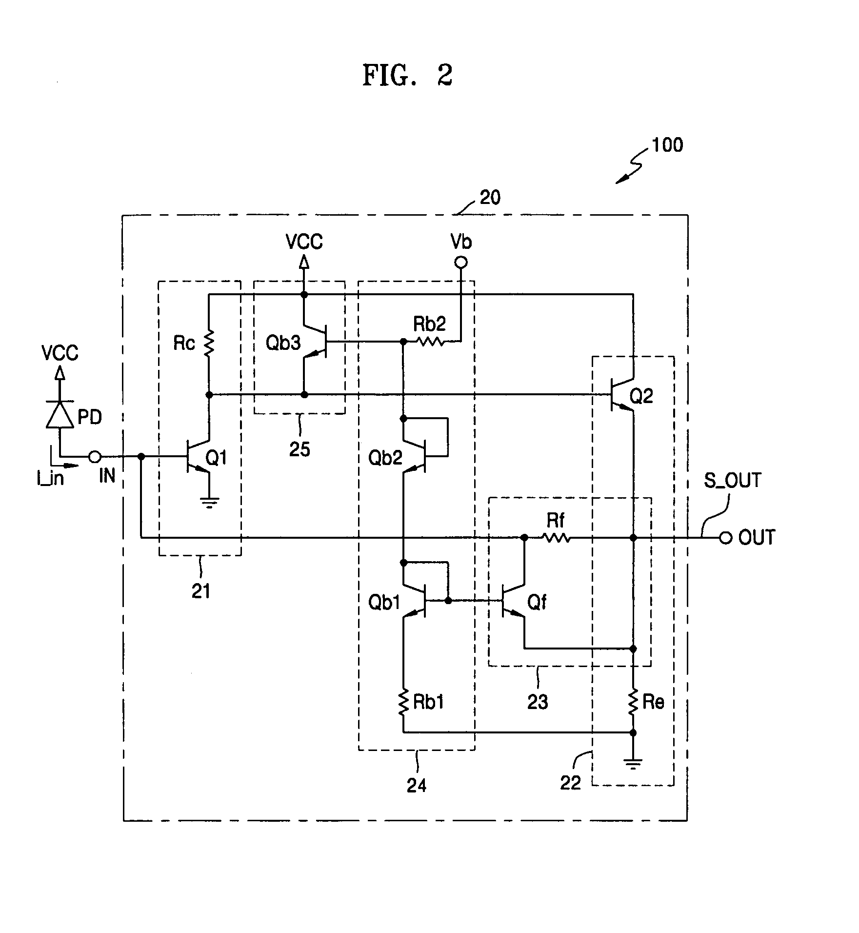
[0027]FIG. 2 is a circuit diagram of a feedback amplifier 100 according to an embodiment of the present invention.

[0028]Referring to FIG. 2, the feedback amplifier 100 includes an input terminal IN, an output terminal OUT, and a feedback amplification unit 20 connected between the input terminal IN and the output terminal OUT.

[0029]The input terminal IN is connected to a power supply VCC and a photodiode is connected between the input terminal IN and the power supply VCC. Accordingly, an input voltage is detected by the photodiode. Also, cathode current of the photodiode PD, which is input current of the amplifier 100, is applied to the input terminal IN.

[0030]The feedback amplification unit 20 amplifies an input voltage and generate an output signal. The feedback amplification unit 20 inc...


PUM


Abstract

There is provided a feedback amplifier capable of easily controlling its dynamic range without a separate gain control signal generation circuit. The feedback amplifier includes an input terminal detecting an input voltage from input current, a feedback amplification unit amplifying the input voltage to generate an output signal, and an output terminal outputting a signal amplified by the feedback amplification unit. The feedback amplification unit includes a feedback circuit unit including a feedback resistor located between the input terminal and the output terminal, and a feedback transistor connected in parallel to the feedback resistor; and a bias circuit unit supplying a predetermined bias voltage to the feedback transistor of the feedback circuit unit and merged in the feedback amplification unit.

Description

BACKGROUND OF THE INVENTION[0001]This application claims the priority of Korean Patent Application No. 10-2003-0083618, filed on Nov. 24, 2003, in the Korean Intellectual Property Office, the disclosure of which is incorporated herein in its entirety by reference.[0002]1. Field of the Invention[0003]The present invention relates to an optical communication system, and more particularly, to a feedback amplifier used as a preamplifier of an optical communication system.[0004]2. Description of the Related Art[0005]A general feedback amplifier includes an amplifier circuit for amplifying an input signal in order to provide an output voltage. In such a feedback amplifier, a feedback circuit for controlling levels of an output voltage signal is provided. The feedback circuit includes a feedback resistor connected between an input terminal and an output terminal and a transistor connected in parallel to the feedback resistor. The transistor receives a control signal through its base. Also,...

Claims


Application Information

Patent Timeline
Patent Type & Authority Patents(United States)
IPC IPC(8): H03F3/08H03G3/02
CPCH03F1/34H03F3/08H03G3/3084H03F3/50H03F3/3432H03G3/02
Inventor LEE, SANG HEUNGKI, HYEON CHEOLKANG, JIN YEONGSHIM, KYU HWANCHO, KYONG IK
Owner ELECTRONICS & TELECOMM RES INST
Why Eureka
Try Eureka