Disk drive employing active braking using inductive sense

Inactive Publication Date: 2007-01-02
WESTERN DIGITAL TECH INC
View PDF12 Cites 118 Cited by
  • Summary
  • Abstract
  • Description
  • Claims
  • Application Information

AI Technical Summary

Benefits of technology

[0009]The present invention may be regarded as a disk drive comprising a disk, a head actuated over the disk, and a spindle motor for rotating the disk, the spindle motor comprising a plurality of windings. Disk control circuitry executes a spin-down operation of the spindle motor by estimating an angul

Problems solved by technology

However, a significant amount of head wear can still occur while dynamic braking

Method used


Image

  • Disk drive employing active braking using inductive sense
  • Disk drive employing active braking using inductive sense
  • Disk drive employing active braking using inductive sense

Examples


Embodiment Construction

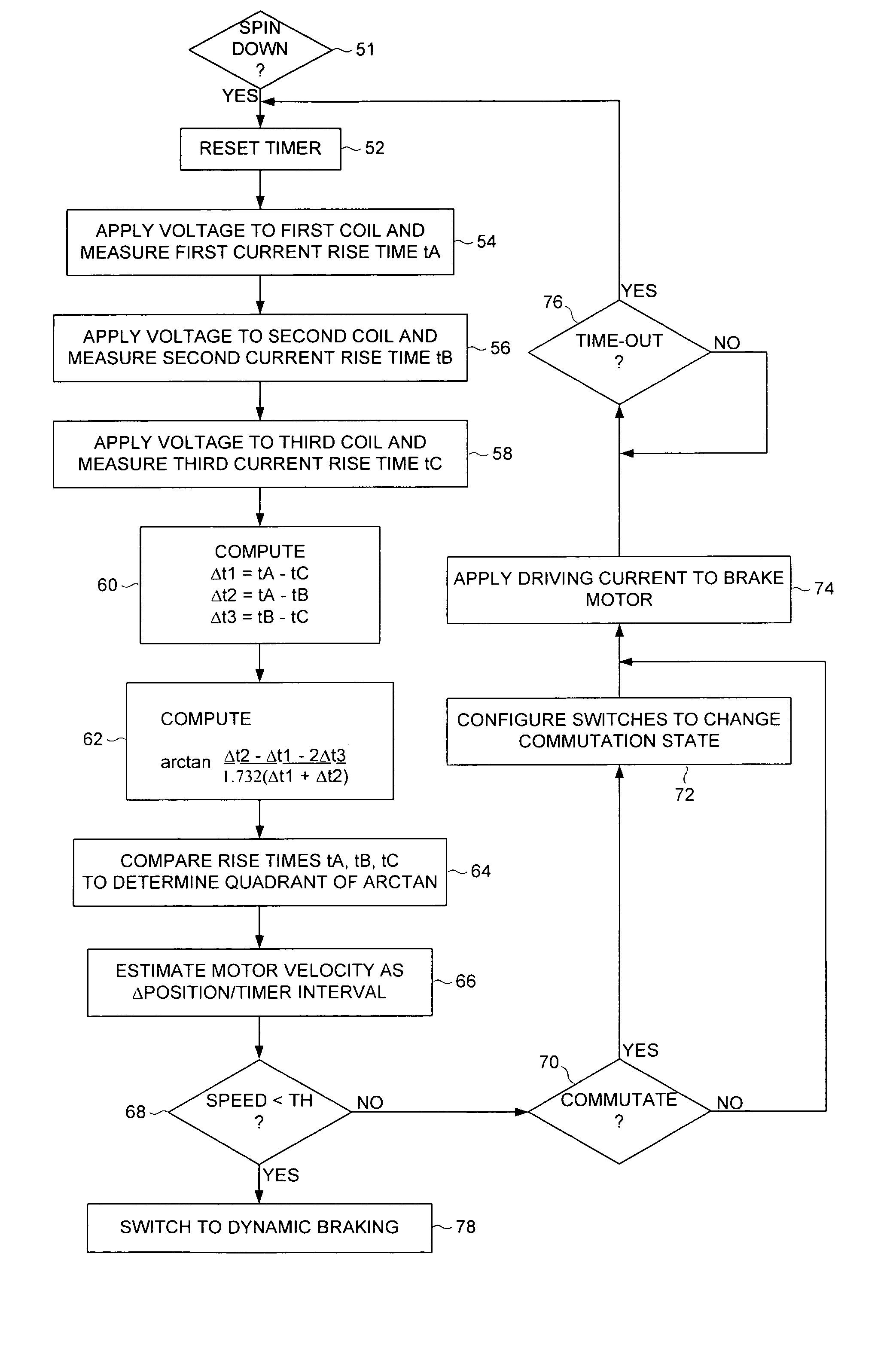
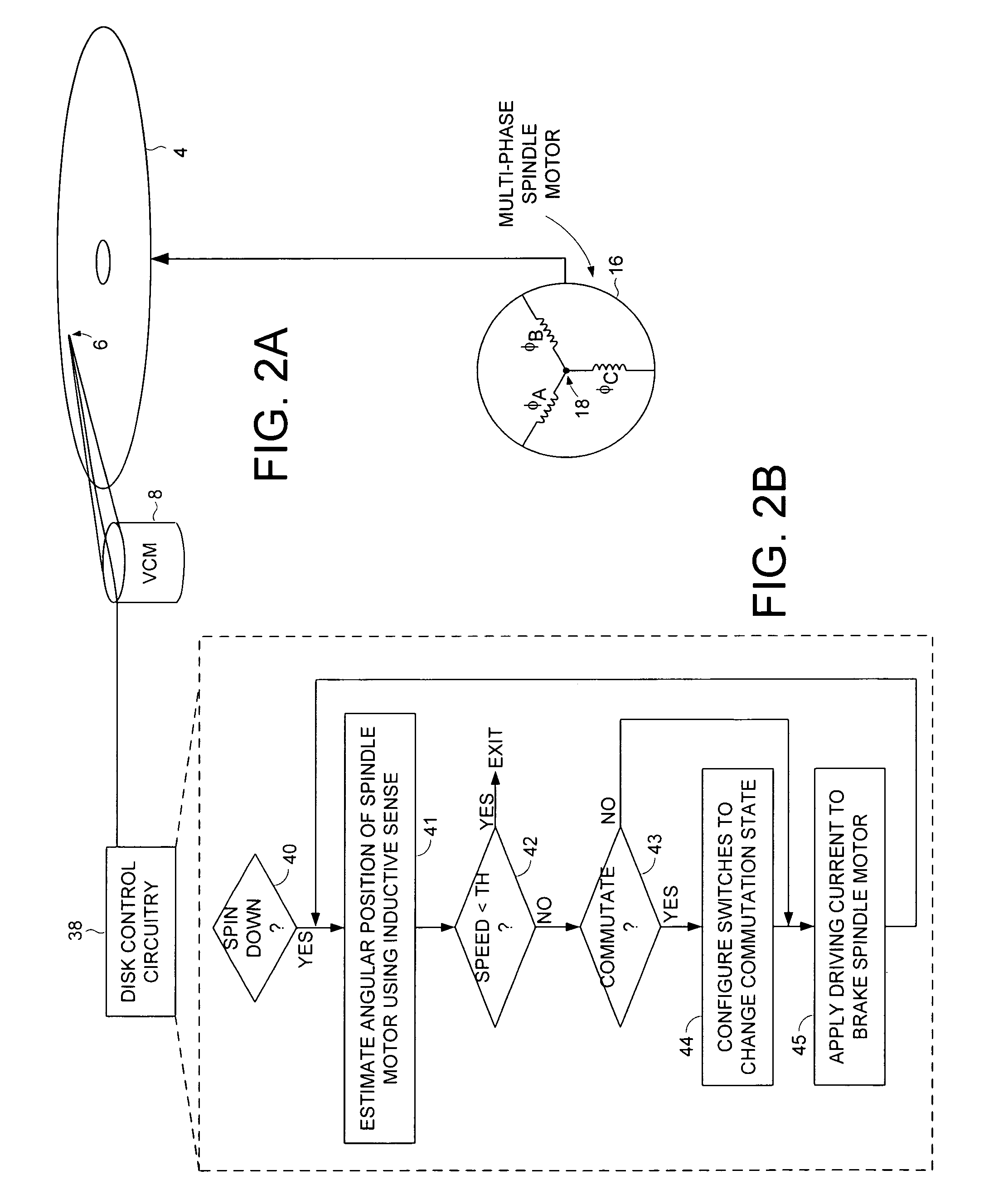
[0026]FIG. 2A shows a disk drive according to an embodiment of the present invention comprising a disk 4, a head 6 actuated over the disk 4, and a spindle motor 16 for rotating the disk 4, wherein the spindle motor 16 comprising a plurality of windings. The disk drive further comprises disk control circuitry 38 for executing a spin-down operation of the spindle motor 16 as shown in the flow diagram of FIG. 2B. If at step 40 a spin-down operation is initiated, at step 41 an angular position of the spindle motor 16 is estimated by applying a voltage to at least one of the windings and evaluating a rise time of current flowing through the winding. If at step 42 an estimated speed of the spindle motor 16 has not fallen to a predetermined threshold (e.g., substantially zero), and at step 43 the estimated angular position indicates the windings should be commutated, at step 44 the windings are commutated. At step 45 a driving current is applied to the windings to brake the spindle motor.

[...


PUM


Abstract

A disk drive is disclosed comprising a disk, a head actuated over the disk, and a spindle motor for rotating the disk, the spindle motor comprising a plurality of windings. Disk control circuitry executes a spin-down operation of the spindle motor by estimating an angular position of the spindle motor by applying a voltage to at least one of the windings and evaluating a rise time of current flowing through the winding. The windings are commutated in response to the estimated angular position, and a driving current is applied to the windings to brake the spindle motor.

Description

BACKGROUND OF THE INVENTION[0001]1. Field of the Invention[0002]The present invention relates to disk drives. More particularly, the present invention relates to a disk drive employing active braking using inductive sense.[0003]2. Description of the Prior Art[0004]FIG. 1 shows a prior art disk drive 2 comprising a disk 4 having a plurality of tracks, a head 6, a voice coil motor 8 for actuating the head 6 radially over the disk 4, and an interface 10 for receiving a primary supply voltage 12 and a secondary supply voltage 14 from a host computer. The disk drive 2 further comprises a multi-phase spindle motor 16 for rotating the disk 4, wherein the multi-phase spindle motor 16 comprises a plurality of windings (e.g., φA, φB, φC) having a first end and a second end, wherein the second ends are connected together at a center tap 18. A spindle driver 20, responsive to the primary supply voltage 12, commutates the windings over commutation intervals. The spindle motor 16 is shown as comp...

Claims


Application Information

Patent Timeline
IPC IPC(8): G11B15/46G11B15/48H02P1/00
CPCG11B19/20H02P6/24G11B19/2063
Inventor RYAN, ROBERT P.
Owner WESTERN DIGITAL TECH INC
Why Eureka
Try Eureka