Spring assisted head stack assembly comb

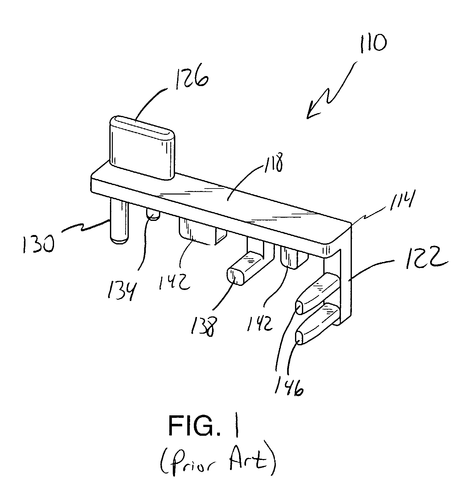
a comb and spring technology, applied in the direction of supporting heads, recording information storage, instruments, etc., can solve the problems of unstable comb b>110/b>, unsuitable head protection fixtures, and undetected contact of heads

Inactive Publication Date: 2007-01-09
MAXTOR
View PDF8 Cites 41 Cited by
  • Summary
  • Abstract
  • Description
  • Claims
  • Application Information

AI Technical Summary

Benefits of technology

[0022]Various refinements exist of the features noted in relation to the second aspect of the present invention. Further features may also be incorporated in the second aspect of the present invention as well. These refinements and additional features may exist individually or in any combination. The head stack assembly for the disk drive may include an actuator body, a plurality of rigid actuator arms that extend from the actuator body, and a separate head gimbal assembly mounted on each actuator arm. Each head gimbal assembly may include a flexible suspension or load beam, a slider, and a head (e.g., one or more transducers) that is carried by the slider. One end of each suspension may be mounted on an end portion of one of the actuator arms, while the slider may be mounted toward an opposite end of the suspension. A given head separator of the comb utilized by the second aspect may engage the suspension of those adjacent pairs of head gimbal assemblies in the head stack assembly that are biased toward each other so as to maintain their corresponding heads in vertically spaced relation. The first portion of the head stack assembly that is initially engaged by the latch (and thereby causes the latch to move from its first position to its second position) may be a side surface of the uppermost actuator arm within the head stack assembly. Movement of the latch from the second position at least back toward the first position may be to allow the latch to engage a lower surface of this uppermost actuator arm within the head stack assembly, to in turn facilitate the retention of the comb on the head stack assembly.

Problems solved by technology

In any case, heads may be damaged by undesired contact prior to be installed in a hard disk assembly having a plurality of vertically spaced computer-readable storage disks.
During a significant number of assembly and disassembly processes associated with the manufacture of the head stack assembly / hard disk assembly, the head protection fixture is not applicable and may not be installed.
One problem is that the comb 110 is unstable when installed on a disk drive head stack assembly having an odd number of head gimbal assemblies.
Another problem with the head stack assembly comb 110 is that without the above-noted head protection fixture, the retention forces for maintaining the comb 110 on the head stack assembly are significantly reduced.
This is an insufficient retention force for many purposes.

Method used


Image

  • Spring assisted head stack assembly comb
  • Spring assisted head stack assembly comb
  • Spring assisted head stack assembly comb

Examples


Embodiment Construction

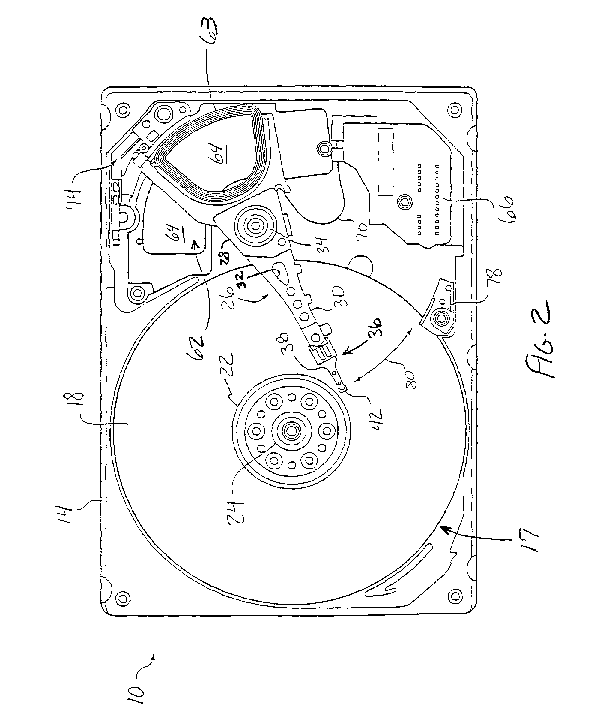
[0053]The present invention will now be described in relation to the accompanying drawings that at least assist in illustrating its various pertinent features. One embodiment of a disk drive 10 is illustrated in FIGS. 2–5. The disk drive 10 generally includes a disk drive housing 16 of any appropriate configuration that defines an enclosed space for the various disk drive components. Here the housing 16 includes a base plate 14 that is typically detachably interconnected with a cover 12. A suitable gasket 13 may be disposed between the cover 12 and the base plate 14 to enhance the seal therebetween.

[0054]The disk drive 10 includes one or more data storage disks 18 of any appropriate computer-readable data storage media. Typically both of the major surfaces of each data storage disk 18 include a plurality of concentrically disposed tracks for data storage purposes. Each disk 18 is mounted on a hub or spindle 22, which in turn is rotatably interconnected with the disk drive base plate...


PUM

PropertyMeasurementUnit
flexibleaaaaaaaaaa
timeaaaaaaaaaa
retention forcesaaaaaaaaaa

Abstract

A head stack assembly comb (154) for maintaining the heads (44) of a head stack assembly (26) in spaced relation is disclosed. The head stack assembly comb (154) includes a comb body (158) and a latch (218). The comb body (158) engages an upper surface of an uppermost actuator arm (30a) in the head stack assembly (26). The latch (218) engages a lower surface of this same actuator arm (30a). When installing the comb (154), the comb (154) is pivoted relative to the head stack assembly (26). This brings the latch (218) into engagement with the noted actuator arm (30a) and causes the latch (218) to pivot in a first direction against a spring (214), and then in the opposite direction by the action of the spring (214) on the latch (218) to engage the latch (218) with the lower surface of the noted actuator arm (30a).

Description

CROSS-REFERENCE TO RELATED APPLICATIONS[0001]This patent application claims priority under 35 U.S.C. §119(e) to U.S. Provisional Patent Application Ser. No. 60 / 432,158, that is entitled “Spring Assisted Head Stack Assembly Comb,” that was filed on Dec. 10, 2002, and the entire disclosure of which is incorporated by reference in its entirety herein.FIELD OF THE INVENTION[0002]The present invention generally relates to the field of disk drives and, more particularly, to a comb that may be utilized to retain various heads of a head stack assembly in spaced relation, including in conjunction with the original assembly and any subsequent rework / rebuild of the head stack assembly, as well as in conjunction with any shipping of the head stack assembly for integration with a hard disk assembly for a disk drive.BACKGROUND OF THE INVENTION[0003]One common basic disk drive design uses multiple, rigid, vertically spaced actuator arms or tips that extend outwardly from a common actuator body. Th...

Claims


Application Information

Patent Timeline
Patent Type & Authority Patents(United States)
IPC IPC(8): G11B5/127H04R31/00
CPCG11B5/40G11B5/4813G11B5/54Y10T29/49028Y10T29/49025Y10T29/49027
Inventor MCMUNIGAL, TOM E.MCCRANDALL, JOHN D.
Owner MAXTOR
Why Eureka
Try Eureka